Automatic Workpiece Edging and Ripping Device and Method

a workpiece and edging technology, applied in the field of automatic workpiece edging and ripping devices and methods, can solve the problems of workpieces falling out of alignment, workpieces cannot be optimum or straight, and the workpiece is unable to maintain the proper orientation of workpieces, so as to reduce ensure the cutting accuracy. , the effect of reducing the time of sawing

Inactive Publication Date: 2011-10-20
BID GRP TECH US INC
View PDF5 Cites 9 Cited by
  • Summary
  • Abstract
  • Description
  • Claims
  • Application Information

AI Technical Summary

Benefits of technology

[0014]The present invention is an improvement over the prior art, as it not only allows for the accurate alignment and cutting of the workp...

Problems solved by technology

Although generally functional, it is very difficult to maintain the proper orientation of the workpiece as it is advanced beneath the saw blades.
Thus, the workpiece is able to fall out of alignment and the resulting sawn edges are neither optimum nor straight.
The major drawback to all of the systems known in the prior art is the slow processing speed and the limited production of cut boards.
While such an approach would seem to allow optimum cutting, in fact it is extremely difficult to maintain the alignment of the workpiece while it is being advanced beneath the saws.
The need to advance the workpiece inhibits the ability to firmly hold the workpiece in th...

Method used


Image

  • Automatic Workpiece Edging and Ripping Device and Method
  • Automatic Workpiece Edging and Ripping Device and Method
  • Automatic Workpiece Edging and Ripping Device and Method

Examples


Embodiment Construction

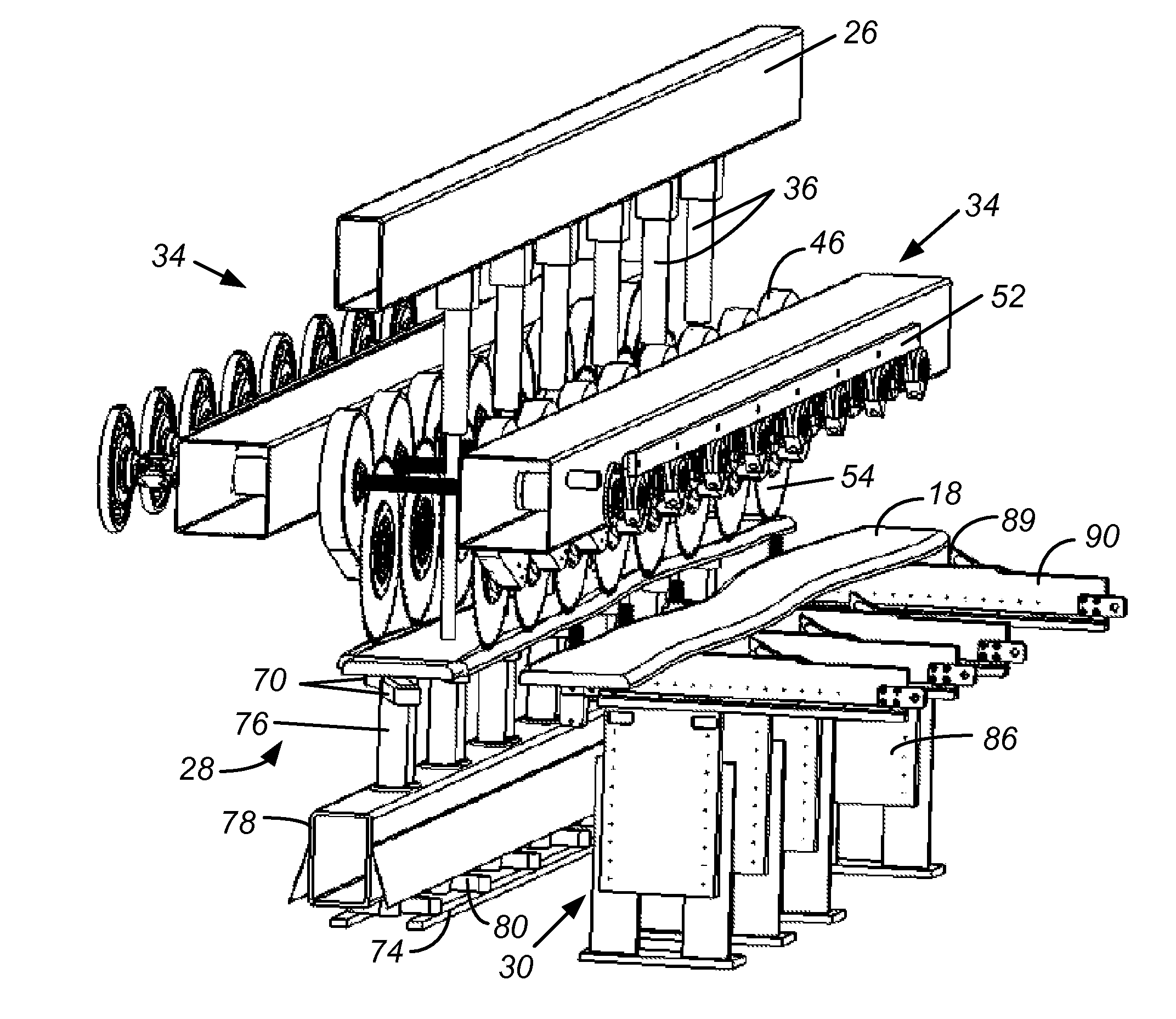
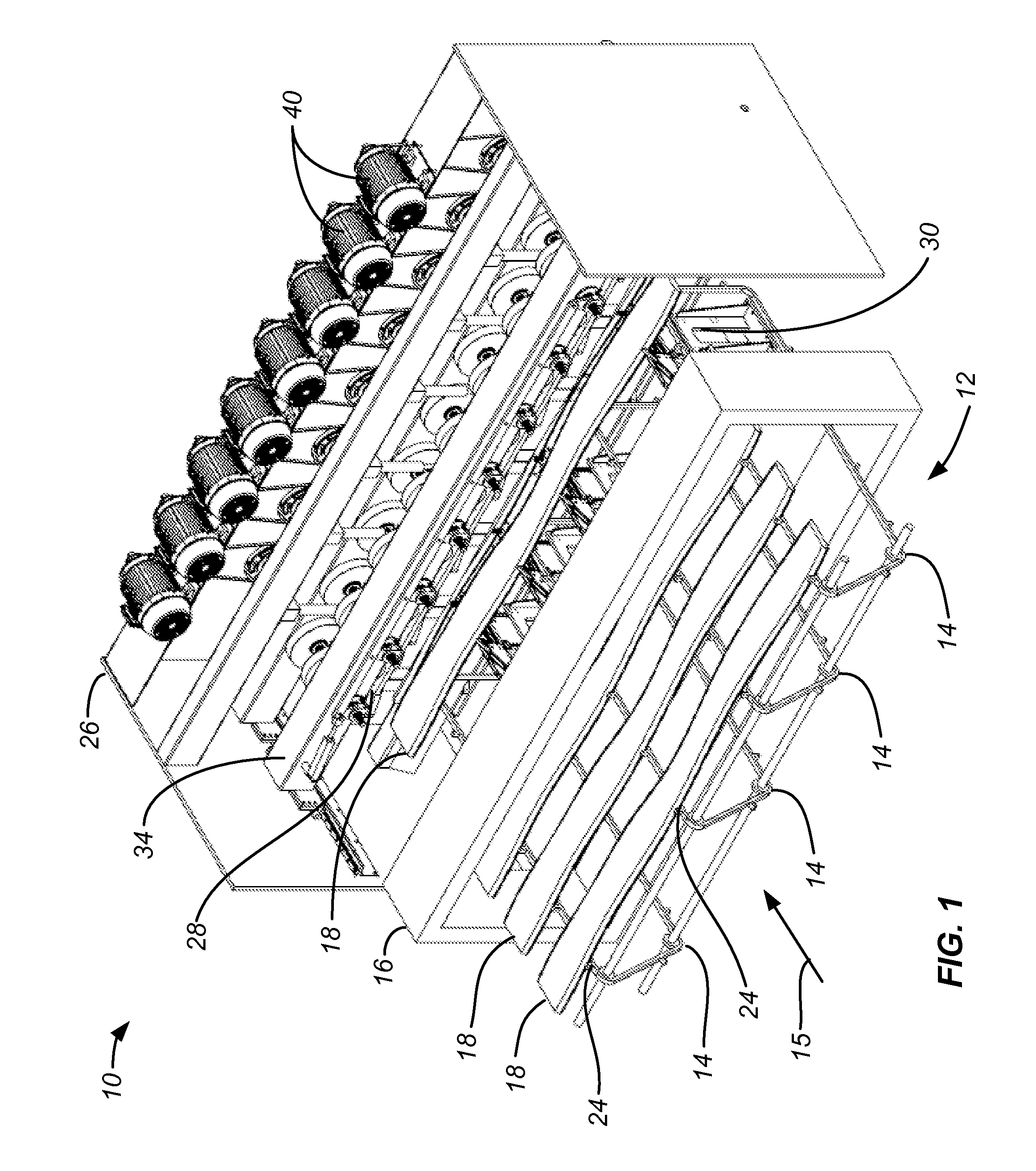
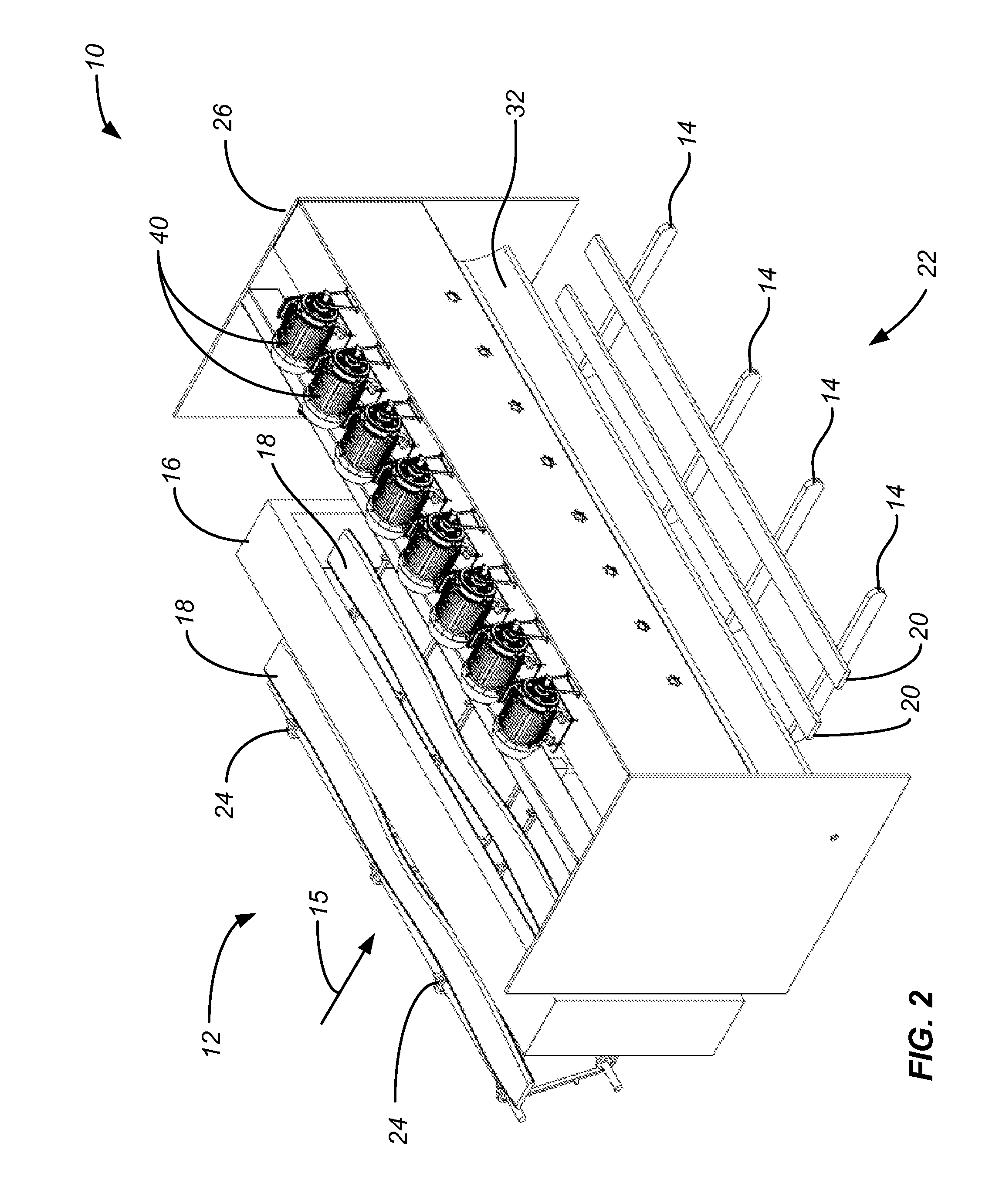
[0049]The following description will typically be with reference to specific structural embodiments and methods. It is to be understood that there is no intention to limit the invention to the specifically disclosed embodiments and methods but that the invention may be practiced using other features, elements, methods and embodiments. Preferred embodiments are described to illustrate the present invention, not to limit its scope, which is defined by the claims. Those of ordinary skill in the art will recognize a variety of equivalent variations on the description that follows. Like elements in various embodiments are commonly referred to with like reference numerals.

[0050]The automatic workpiece edging and ripping system associated with the present invention includes four major sub-systems. First, a conveyor sub-system is provided for advancing workpieces along a substantially straight path in a generally transverse direction relative to their elongated axis. The conveyor sub-system...


PUM

PropertyMeasurementUnit
Lengthaaaaaaaaaa
Pressureaaaaaaaaaa
Lengthaaaaaaaaaa

Abstract

A sawing apparatus for a wood products sawing system comprises a frame, a sawing table, a workpiece clamping element, and an overhead saw assembly. A workpiece can be supported on the sawing table and releasably secured to the table by the workpiece clamping element. The overhead saw array is supported by the frame and includes a saw driver and a row of at least three saw assemblies so to sever the workpiece along the cut line by movement of the saw blades along two dimensional paths. A variable width sawing table comprises a driving assembly and a row of support arm assemblies mounted to the frame member and coupled to the driving assembly for movement to at least first and second positions.

Description

BACKGROUND OF THE INVENTION[0001]1. Field of the Invention[0002]The present invention relates generally to sawmill equipment, and more particularly to an apparatus and method finding particular utility for ripsawing a workpiece to remove the waste wane edges therefrom and expose an optimum usable board area.[0003]2. Description of the Prior Art[0004]In sawmill operations, an incoming log is typically cut along a number of parallel, axial planes to yield a number of irregularly shaped planks referred to as side boards or workpieces. The length of the workpiece is determined by the length of the log from which it was cut and is the same for all workpieces cut from the same log. The width of each workpiece, however, will vary depending on the particular section of the log which was cut. Workpieces which are derived from the central core of the log will be much wider than those derived from the edge of the log. Moreover, the workpieces will generally taper in one direction corresponding...

Claims


Application Information

Patent Timeline
IPC IPC(8): B27B5/18B27B5/29B27B1/00
CPCB23D45/027B23D45/042B23D45/105B23D47/04B27B31/00B27B5/18B27B5/185B27B5/187B27B5/04
Inventor MCGEHEE, RONALD W.
Owner BID GRP TECH US INC
Why Eureka
Try Eureka