Shielded trench mosfet with multiple trenched floating gates as termination

a technology of mosfet and termination gate, which is applied in the field of shielded trench mosfet with multiple trenched floating gate termination gate, can solve the problems of encountering technical problems in the structure of trench metal-oxide-semiconductor-field-effect-transistors (mosfets) having trenched floating gate termination in the prior ar

Active Publication Date: 2011-10-20
FORCE MOS TECH CO LTD
View PDF2 Cites 58 Cited by
  • Summary
  • Abstract
  • Description
  • Claims
  • Application Information

AI Technical Summary

Benefits of technology

[0017]Preferred embodiments include one or more of the following features. Said trenched source-body contacts and said trenched gate contacts are filled with Ti/TiN/W or Co/TiN/W metal plugs connecting with a resistanc

Problems solved by technology

Typical structures of trench metal-oxide-semiconductor-field-effect-transistors (MOSFETs) hav

Method used


Image

  • Shielded trench mosfet with multiple trenched floating gates as termination
  • Shielded trench mosfet with multiple trenched floating gates as termination
  • Shielded trench mosfet with multiple trenched floating gates as termination

Examples


Embodiment Construction

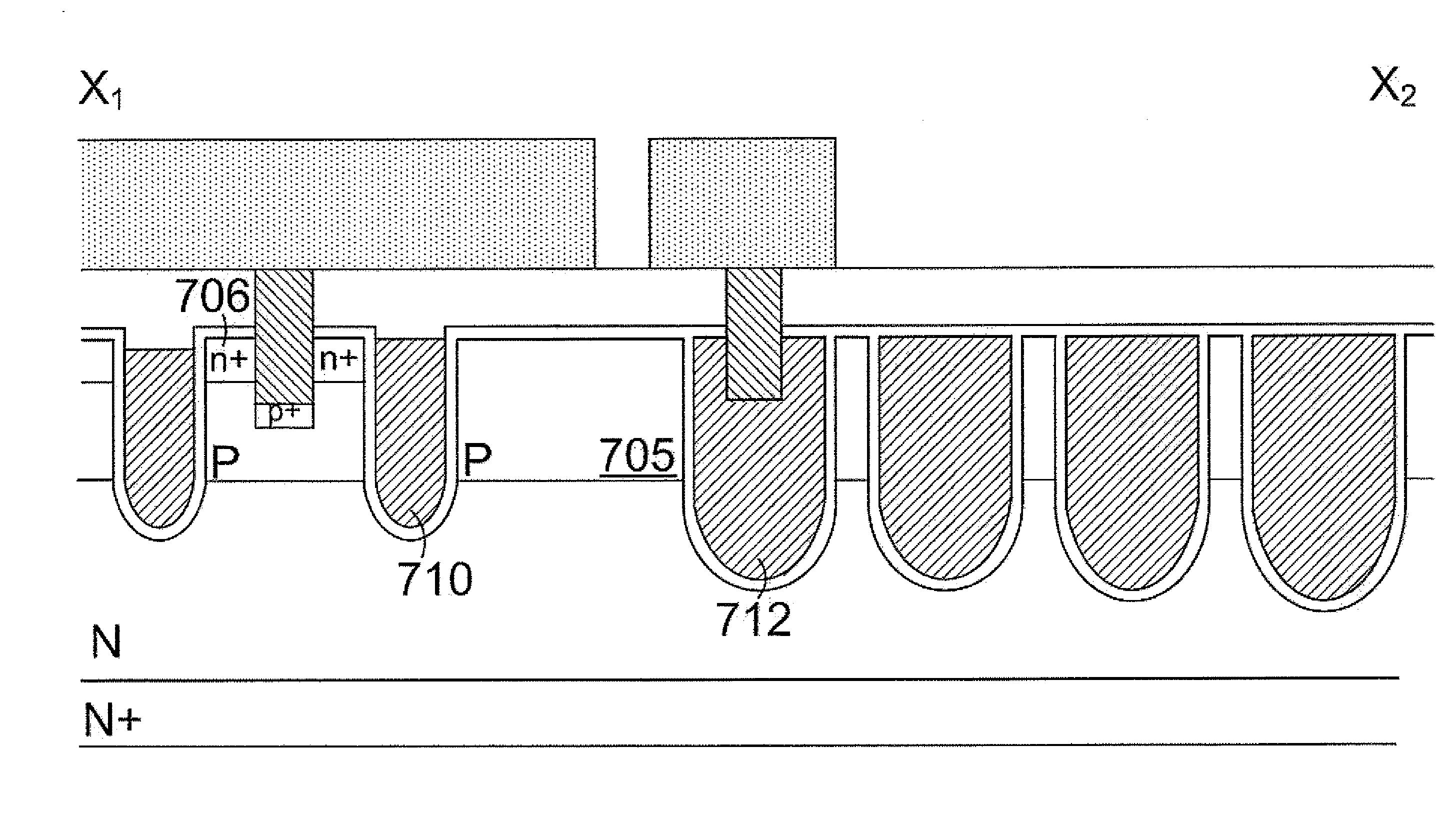
[0040]Please refer to FIG. 3 for a preferred embodiment of this invention wherein an N-channel trench MOSFET cell is formed on an N+ substrate 200 with a metal layer 290 on the rear side as drain. Inside an N epitaxial layer 202 onto the N+ substrate 200, a plurality of first type trenched gates 210 are formed in active area, at least a second type trenched gate 212 having greater trench width and depth is formed for gate connection, and a plurality of third type trenched floating gates 211 are formed in termination area. The first type trenched gates 210, the second type trenched gate 212 and the third type trenched floating gates 211 are each filled with a doped poly-silicon layer padded by a gate oxide layer 208 as a single gate electrode. Furthermore, the third type trenched floating gates 211 have same trench width which are the same as the first type trenched gates 210 in the active area, meanwhile, the trench space between every two adjacent of the third type trenched floatin...


PUM


Abstract

A trench MOSFET comprising a plurality of transistor cells having shielded trenched gates and multiple trenched floating gates as termination region is disclosed. The trenched floating gates have trench depth equal to or deeper than body junction depth of body regions in termination area. In some preferred embodiments, the trenched floating gates in the termination area are implemented by using shielded electrode structure.

Description

CROSS REFERENCE TO RELATED APPLICATIONS[0001]This application is a continuation-in-part (CIP) of U.S. application Ser. No. 12 / 591,467, filed on Nov. 20, 2009.FIELD OF THE INVENTION[0002]This invention relates generally to the cell structure, device configuration and fabrication process of power semiconductor devices. More particularly, this invention relates to a novel and improved cell structure, device configuration and improved process for fabricating trench metal-oxide-semiconductor-field-effect-transistors (MOSFETs) with trenched floating gates as termination to maintain a high breakdown voltage and to achieve a lower gate-to-drain charge Qgd and lower fabrication cost.BACKGROUND OF THE INVENTION[0003]Typical structures of trench metal-oxide-semiconductor-field-effect-transistors (MOSFETs) having trenched floating gates as termination in prior arts are encountering technical problems. For example, in U.S. Pat. No. 6,462,376, a trench MOSFET was disclosed with n+ source regions ...

Claims


Application Information

Patent Timeline
IPC IPC(8): H01L29/78
CPCH01L21/823481H01L21/823487H01L29/407H01L29/41766H01L29/4236H01L29/456H01L29/1095H01L29/66734H01L29/7811H01L29/7813H01L29/0619H01L29/0696H01L29/0878H01L29/66727
Inventor HSIEH, FU-YUAN
Owner FORCE MOS TECH CO LTD
Why Eureka
Try Eureka