
Collapsible Lighting Device

Inactive Publication Date: 2011-10-20
PENOYER GREGORY JAMES
View PDF10 Cites 28 Cited by
  • Summary
  • Abstract
  • Description
  • Claims
  • Application Information

AI Technical Summary

Benefits of technology

[0004]A collapsible lighting device can solve many of the problems posed by conventional flashlights. Flashlights work well when a relatively small focused area of illumination is needed for a particular work area. They become limited when a wide area of illumination is required, such as the underside of an automobile or behind a piece of equipment for example. As flashlights typically only have one light bulb which is focused by a reflective lens, they typically only illuminate a small area. By utilizing a plurality of light emitting elements, a collapsible lighting device can illuminate a significantly larger work area.
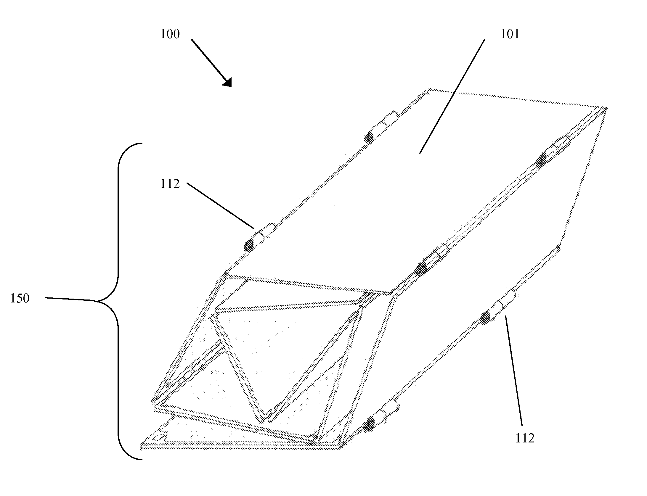
[0007]In addition, to improve on the userability of a lighting device, a collapsible lighting device can be designed to be thin and low profile so that it can be used in tight spaces like under an automobile or between a wall and a large piece of equipment. Further, a collapsible lighting device can be manufactured from flexible materials such that it does not require a large flat surface to be placed on, as often work areas are not conducive to large, flat, stable surfaces. To compliment the thin design, a collapsible lighting device can be designed with mounting tabs and magnets built in to allow for temporary positioning in a variety of applications.

Problems solved by technology

They become limited when a wide area of illumination is required, such as the underside of an automobile or behind a piece of equipment for example.
Flashlights are generally are hard to position and hold in place when aiming the single beam of light at a particular work area.
They require precise positioning to illuminate a desired area which can be difficult for a user, and sometimes can be impossible given the space envelope surrounding the work area.
Although large arrays of light emitting elements can provide a larger area of illumination, a very large rigid device would be awkward and difficult to handle by a user.
Also, portability and transportation concerns exist.

Method used


Image

  • Collapsible Lighting Device
  • Collapsible Lighting Device
  • Collapsible Lighting Device

Examples


Embodiment Construction

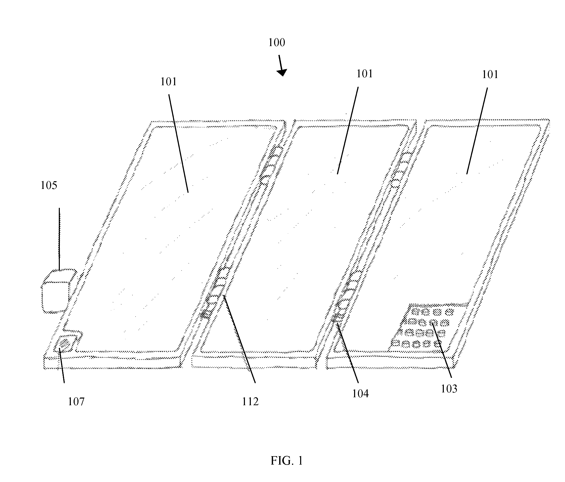
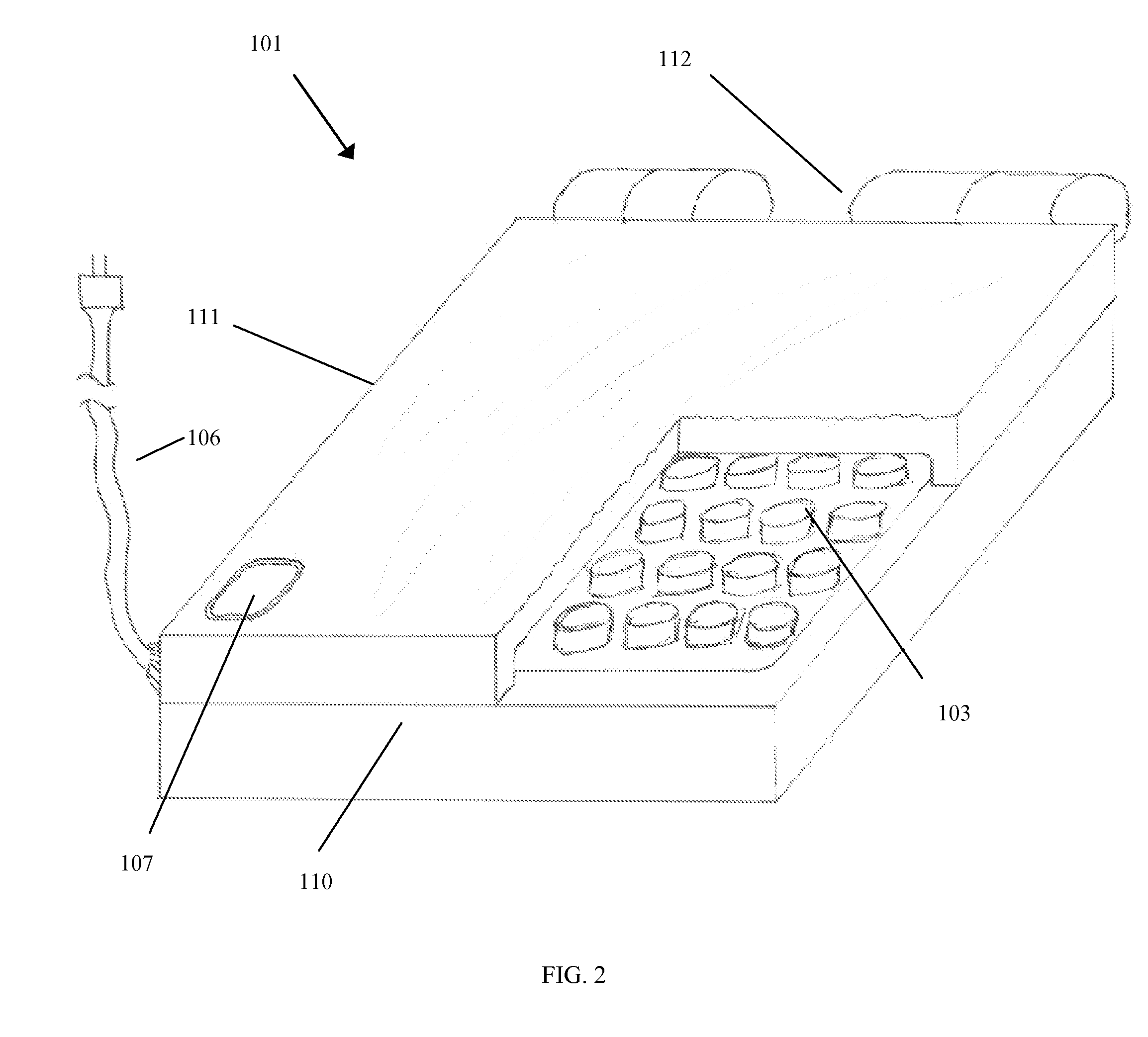
[0038]FIG. 1 is a perspective view of a fully expanded lighting device. A lighting device 100 can comprise one or more light panels 101 each having a plurality of light emitting elements 103. The light emitting elements 103 of the light panels 103 can be powered by an electrical power source 105, such as, a rechargeable battery pack comprising one or more individual batteries, a solar power panel, a fuel cell, or an internal electrical generator. In another embodiment, the light emitting elements 103 of the light panels 101 can be powered by AC electrical power.

[0039]The lighting device 100 can further comprise an electronic control system 107 that is configured to control the distribution of electrical power to the light emitting elements 103 of the one or more light panels 101. In one embodiment, the electronic control system 107 comprises a simple on / off operational switch or a control dial. Further, the electronic control system 107 can comprise an LED driver circuit that can ma...


PUM


Abstract

A collapsible lighting device including a plurality of light panel sections, each light panel section comprising a plurality of light emitting elements, at least one connection element constructed and arranged to connect one or more light panel sections of the plurality of light panel sections to one another, and an electronic control system configured to distribute electrical power to the plurality of light emitting elements.

Description

RELATED APPLICATIONS[0001]This application claims the benefit of U.S. Provisional Patent Application Ser. No. 61 / 325,412, filed on Apr. 19, 2010, the content of which is incorporated herein by reference in its entirety.TECHNICAL FIELD[0002]The present invention generally provides an improved lighting device, and more particularly an improved lighting device of the type commonly used for temporary lighting.BACKGROUND OF THE INVENTION[0003]Flashlights have been long known and widely used. Although simple flashlights have been generally effective for many required applications, such as illuminating small work areas in dimly lit locations with a generally large space envelope surrounding them. However, their abilities are often limited by size. Generally, whenever a larger area of illumination is required, a larger flashlight is required. When a larger flashlight is used, the space envelope around any particular work area is also required.SUMMARY OF THE INVENTION[0004]A collapsible ligh...

Claims


Application Information

Patent Timeline
IPC IPC(8): H05B37/02F21L4/02F21V5/00F21S4/00
CPCF21S2/005F21V17/007F21Y2105/008F21Y2101/02F21Y2105/001F21V21/30F21Y2105/00F21Y2105/10F21Y2115/10F21Y2115/15
Inventor PENOYER, GREGORY JAMES
Owner PENOYER GREGORY JAMES
Learn More