
Electrophoretic display device and method for driving the same

a display device and display technology, applied in the field of electrotrophoretic display devices, can solve the problems of limiting the failure to increase the display image quality, and achieve the effect of increasing the number of gray levels

Inactive Publication Date: 2011-10-20
CHUNGHWA PICTURE TUBES LTD
View PDF3 Cites 5 Cited by
  • Summary
  • Abstract
  • Description
  • Claims
  • Application Information

AI Technical Summary

Benefits of technology

[0006]A primary objective of the present invention is to provide an electrophoretic display device and a method for driving the same, which are capable of increasing the number of gray levels being displayed by the electrophoretic display device.
[0009]The electrophoretic display device and the method for driving the same according to the present invention provide a plurality of driving voltages to increase various locations of the charged particles. As a result, an object of increasing the number of gray levels being displayed by the electrophoretic display device can be achieved.

Problems solved by technology

However, a frame rate of the electrophoretic display device limits the number of gray levels which the electrophoretic display device can display.
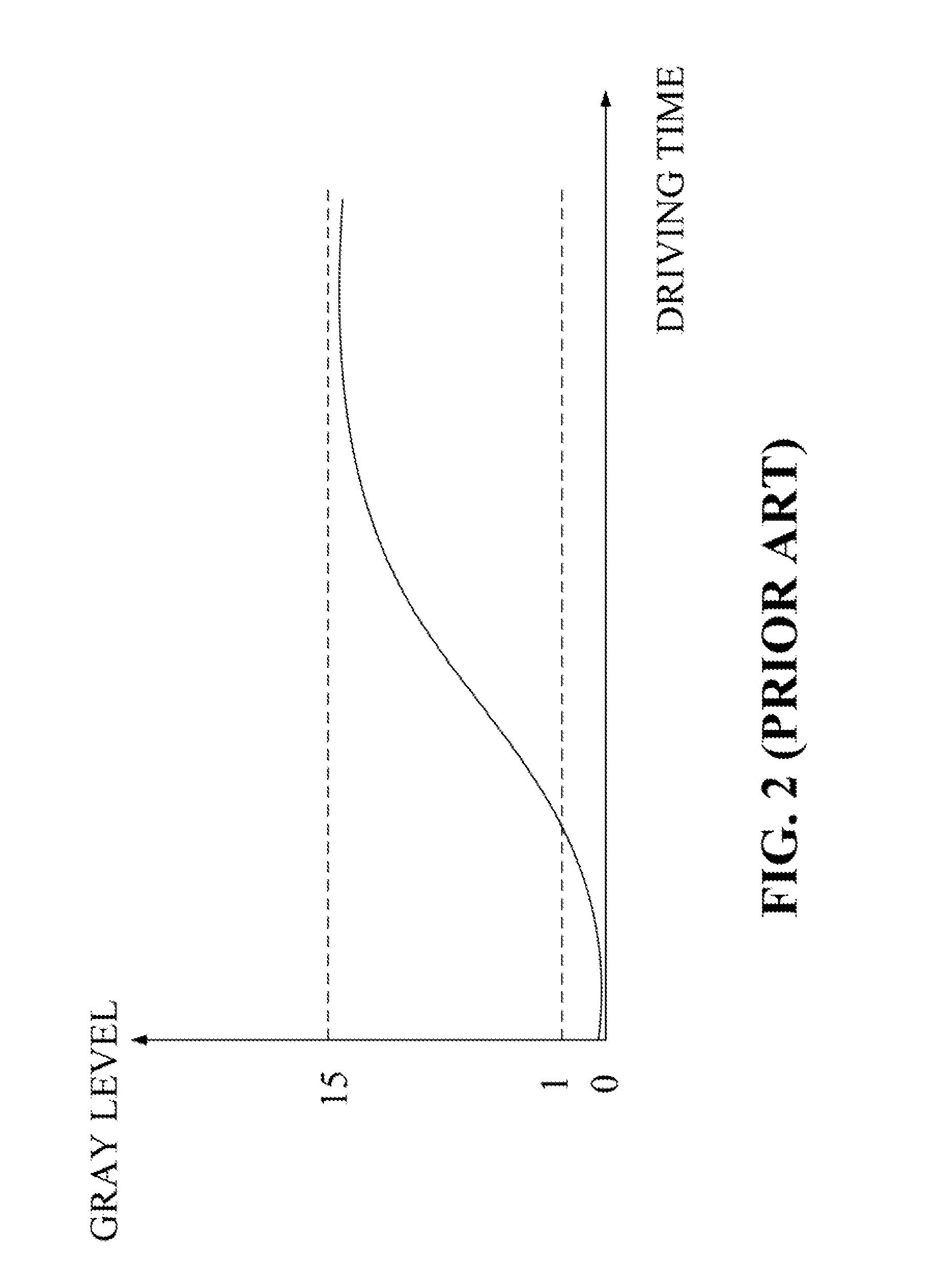
As a result, only 16 gray levels (from gray level 0 to gray level 15) can be displayed at the frame rate of 50 Hz, and the electrophoretic display device fails to display more gray levels so that the display image quality fails to be increased.

Method used


Image

  • Electrophoretic display device and method for driving the same
  • Electrophoretic display device and method for driving the same
  • Electrophoretic display device and method for driving the same

Examples


Embodiment Construction

[0018]Please refer to FIG. 4, which illustrates a system architecture of a method for driving an electrophoretic display device 400 according to an embodiment of the present invention. The electrophoretic display device 400 comprises a controller 410, a power supply unit 420, a source driving circuit 430, a gate driving circuit 440, and an electrophoretic display panel 450. The electrophoretic display panel 450 comprises a first glass substrate 452, a first electrode layer 454, an electrophoretic layer 456, a second electrode layer 458, and a second glass substrate 462. In the present embodiment, the first electrode layer 454 is an indium tin oxide (ITO) layer being manufactured onto the first glass substrate 452. The second electrode layer 458 is an ITO layer being manufactured onto the second glass substrate 462. The second electrode layer 458 may be regarded as a common electrode layer corresponding to the first electrode layer 454. An electric field drives a plurality of charged...


PUM


Abstract

An electrophoretic display device and a method for driving the same are disclosed. The electrophoretic display device includes a plurality of pixels, a first electrode layer, a second electrode layer, a driving voltage generating unit, and an electrophoretic layer disposed between the first electrode layer and the second electrode layer. The driving voltage generating unit is capable of providing a plurality of various driving voltages to drive charged particles in the electrophoretic layer, so as to increase the number of gray levels displayed by the electrophoretic display device.

Description

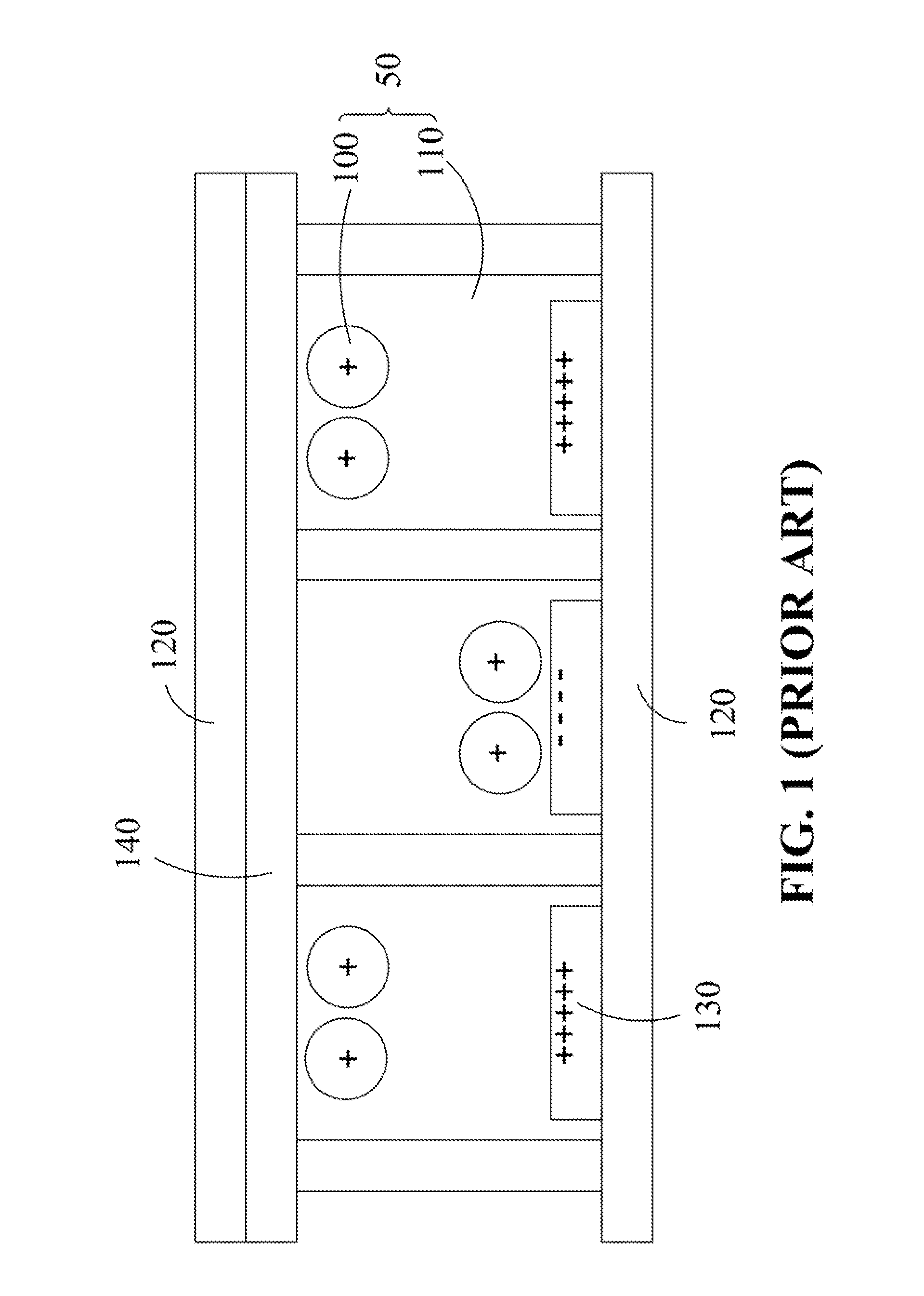
TECHNICAL FIELD OF THE INVENTION[0001]The present invention relates to an electrophoretic display device, and more particularly to an electrophoretic display device and a method for driving the same.BACKGROUND OF THE INVENTION[0002]Please refer to FIG. 1, which illustrates a conventional electrophoretic display device display principle. An electrophoretic layer 50 is sealed between two films 120 for displaying images. The electrophoretic layer 50 comprises a plurality of charged particles 100 and a solution 110 for suspending the charged particles 100. In the electrophoretic layer 50, the charged particles 100 are driven by an electric field formed between the first electrode 130 and the second electrode 140, so as to change locations of the charged particles 100 for displaying different gray levels.[0003]Please refer to FIG. 2 and FIG. 3. FIG. 2 illustrates a graph showing a relationship between the driving time and the gray level in the conventional electrophoretic display device....

Claims


Application Information

Patent Timeline
Patent Type & Authority Applications(United States)
IPC IPC(8): G09G5/00
CPCG09G5/00G09G2330/028G09G2310/027G09G3/344
Inventor LU, CHI-MINGCHEN, HUNG-HSIANGCHU, YI-NAN
Owner CHUNGHWA PICTURE TUBES LTD
Learn More