Moving object detection apparatus and moving object detection method

Active Publication Date: 2011-10-20
PANASONIC CORP
View PDF2 Cites 42 Cited by
  • Summary
  • Abstract
  • Description
  • Claims
  • Application Information

AI Technical Summary

Benefits of technology

[0025]According to the present invention, it is possible to correctly perform region extraction at high speed, with a smaller amount of calculation, on an image including a moving object that moves changing shape such as a perso

Problems solved by technology

However, the conventional technique of region extraction as described above has a problem of not allowing accurate extraction of a moving object in such cases as where the moving object is partially occluded by another moving object or where moving objects significantly different from each other in size are included.
In performing this, unless the moving object region is not appropriately extracted, it is not possible to correctly apply the model obtained by parameterizing the moving object, to the moving object region candidate.
Particularly, in the scenes as described above, it is difficult to appropriately extract the moving region candidate.
Furthermore, even if the moving object region candidate is appropriately extracted, there is yet another problem as follows.
This ind

Method used


Image

  • Moving object detection apparatus and moving object detection method
  • Moving object detection apparatus and moving object detection method
  • Moving object detection apparatus and moving object detection method

Examples


Example

First Embodiment

[0085]The following will describe a first embodiment of the present invention with reference to the drawings.

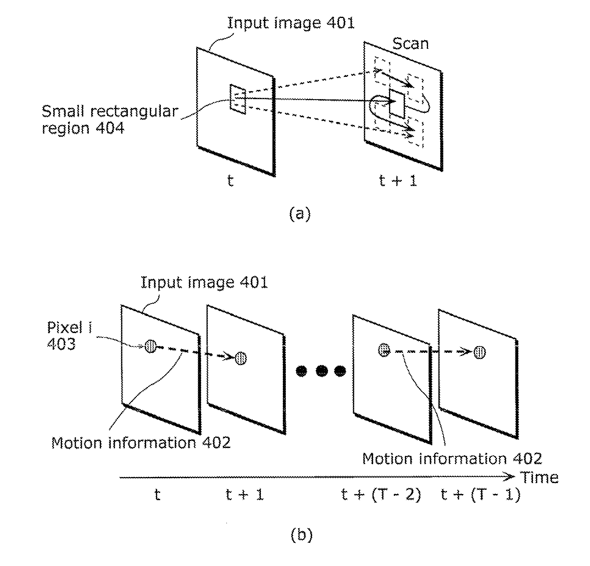
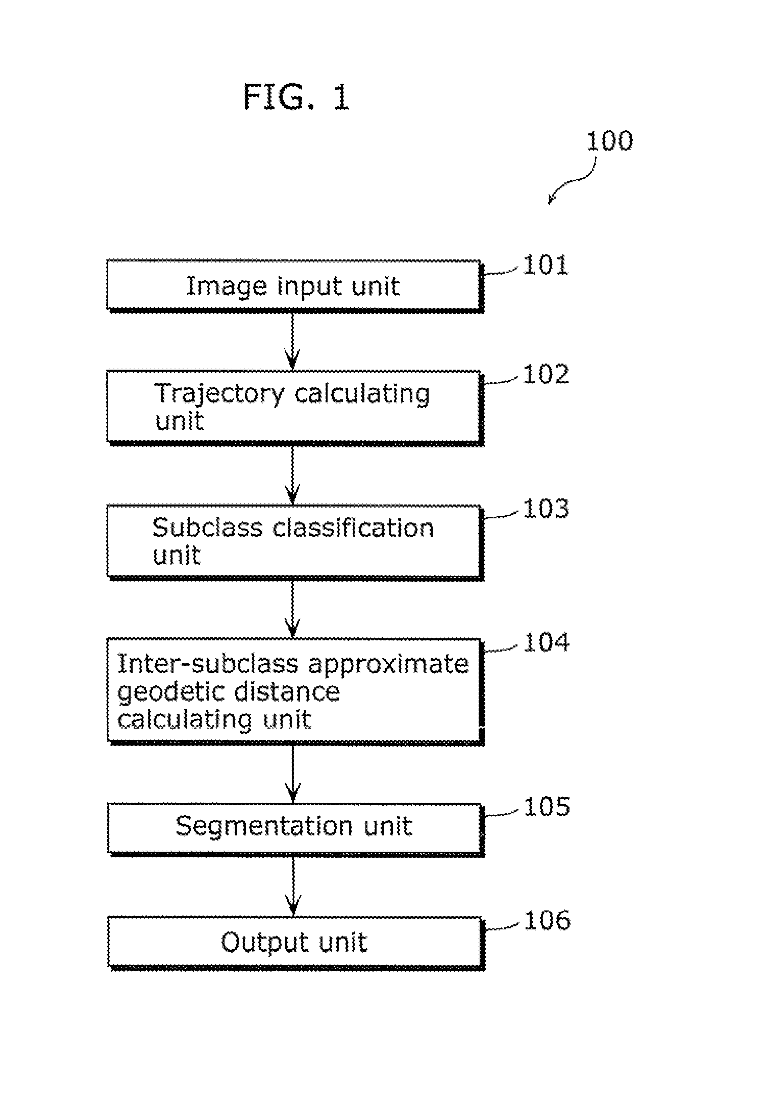
[0086]FIG. 1 is a diagram showing a configuration of a moving object detection apparatus 100 according to an embodiment of the present invention. As shown in FIG. 1, the moving object detection apparatus 100 includes: an image input unit 101, a trajectory calculating unit 102, a subclass classification unit 103, an inter-subclass approximate geodetic distance calculating unit 104, a segmentation unit 105, and an output unit 106. The moving object detection apparatus 100 is an apparatus which detects a moving object in video by performing segmentation to specify all or part of regions of the moving object in the video. In other words, the moving object detection apparatus 100 detects the moving object in the video by performing classification (clustering) to specify all or part of the regions of the moving object in the video, using trajectories made up of corr...

Example

Second Embodiment

[0193]Next, a moving object detection apparatus according to a second embodiment of the present invention will be described.

[0194]Here, an example is described in which the subclass classification processing is performed by the subclass classification unit 103 in a different manner from the manner described in the first embodiment. FIG. 10 is a diagram showing a configuration of a moving object detection apparatus 100a according to the second embodiment of the present invention.

[0195]The moving object detection apparatus 100a according to the second embodiment includes: an image input unit 101, a trajectory calculating unit 102, a subclass classification unit 103a, an inter-subclass approximate geodetic distance calculating unit 104, a segmentation unit 105, and an output unit 106.

[0196]Such a moving object detection apparatus 100a according to the second embodiment has the same configuration as the moving object detection apparatus 100 according the first embodimen...

Example

Third Embodiment

[0210]Next, a moving object detection apparatus according to a third embodiment of the present invention will be described.

[0211]In the third embodiment, in addition to the first and second embodiments, whether or not to synthesize subclasses is determined based on temporal variation in the inter-subclass approximate geodetic distance.

[0212]Since the moving object detection apparatus 100 according to the third embodiment has the same configuration as the moving object detection apparatus 100 according to the first embodiment as shown in FIG. 1, the description of each constituent element will be omitted. However, the processing performed by the segmentation unit 105 is different from the processing in the first embodiment. The following will describe the third embodiment centering on the differences from the first embodiment.

[0213]Hereinafter, an operation of the moving object detection apparatus 100 according to the third embodiment of the present invention will be ...


PUM


Abstract

A moving object detection apparatus includes: an image input unit which receives a plurality of pictures included in video; a trajectory calculating unit which calculates a plurality of trajectories from the pictures; a subclass classification unit which classifies the trajectories into a plurality of subclasses; an inter-subclass approximate geodetic distance calculating unit which calculates, for each of the subclasses, an inter-subclass approximate geodetic distance representing similarity between the subclass and another subclass, using an inter-subclass distance that is a distance including a minimum value of a linear distance between each of trajectories belonging to the subclass and one of trajectories belonging to the other subclass; and a segmentation unit which performs segmentation by determining, based on the calculated inter-subclass approximate geodetic distance, a set of subclasses including similar trajectories as one class.

Description

CROSS REFERENCE TO RELATED APPLICATION[0001]This is a continuation application of PCT application No. PCT / JP2010 / 007480 filed on Dec. 24, 2010, designating the United States of America.BACKGROUND OF THE INVENTION[0002](1) Field of the Invention[0003]The present invention relates to an image processing technique of detecting a moving object by specifying a region in the moving object in an image. Particularly, the present invention relates to a moving object detection apparatus or the like which detects a moving object at high speed based on motion information in video even when the moving object to be detected moves changing shape like a person.[0004](2) Description of the Related Art[0005]Conventionally, research and development has been widely promoted on, a region extraction method for detecting a moving object by extracting, from an image including a moving object (hereinafter, simply referred to as a “moving object”), a region of the moving object within the image. Particularly...

Claims


Application Information

Patent Timeline
IPC IPC(8): G06K9/00
CPCG06K9/00348G06T7/2006G06T2207/30241G06T2207/30196G06T7/2013G06T7/215G06T7/223G06V40/25
Inventor IWASAKI, MASAHIRONOBORI, KUNIOKOMOTO, AYAKO
Owner PANASONIC CORP
Why Eureka
Try Eureka