
Cutting Tool and Cutting Insert Therefor

a cutting tool and insert technology, applied in the direction of tool holders, shaping cutters, manufacturing tools, etc., can solve the problems of undesirably large distance, difficult and time-consuming machining operations,

Active Publication Date: 2011-10-20
ISCAR LTD
View PDF3 Cites 28 Cited by
  • Summary
  • Abstract
  • Description
  • Claims
  • Application Information

AI Technical Summary

Problems solved by technology

As the insert holder is configured with narrower acute angled ridges longitudinally extending between the wider obtuse angled first contact surfaces, undesirably difficult and time-consuming machining operations may be required to manufacture the insert holder.
Also, as the ridges and flutes longitudinally extend between the first and second contact surfaces of the V-shaped male and female parts, respectively, this may necessitate an undesirably large distance between the two laterally spaced-apart clamping contact locations on each of the V-shaped male and female parts.
As the cutting insert is configured with the second pair of contacting positions between the first pair of contacting positions in the width direction, this may necessitate an undesirably large distance between the first pair of contacting positions.

Method used


Image

  • Cutting Tool and Cutting Insert Therefor
  • Cutting Tool and Cutting Insert Therefor
  • Cutting Tool and Cutting Insert Therefor

Examples


Embodiment Construction

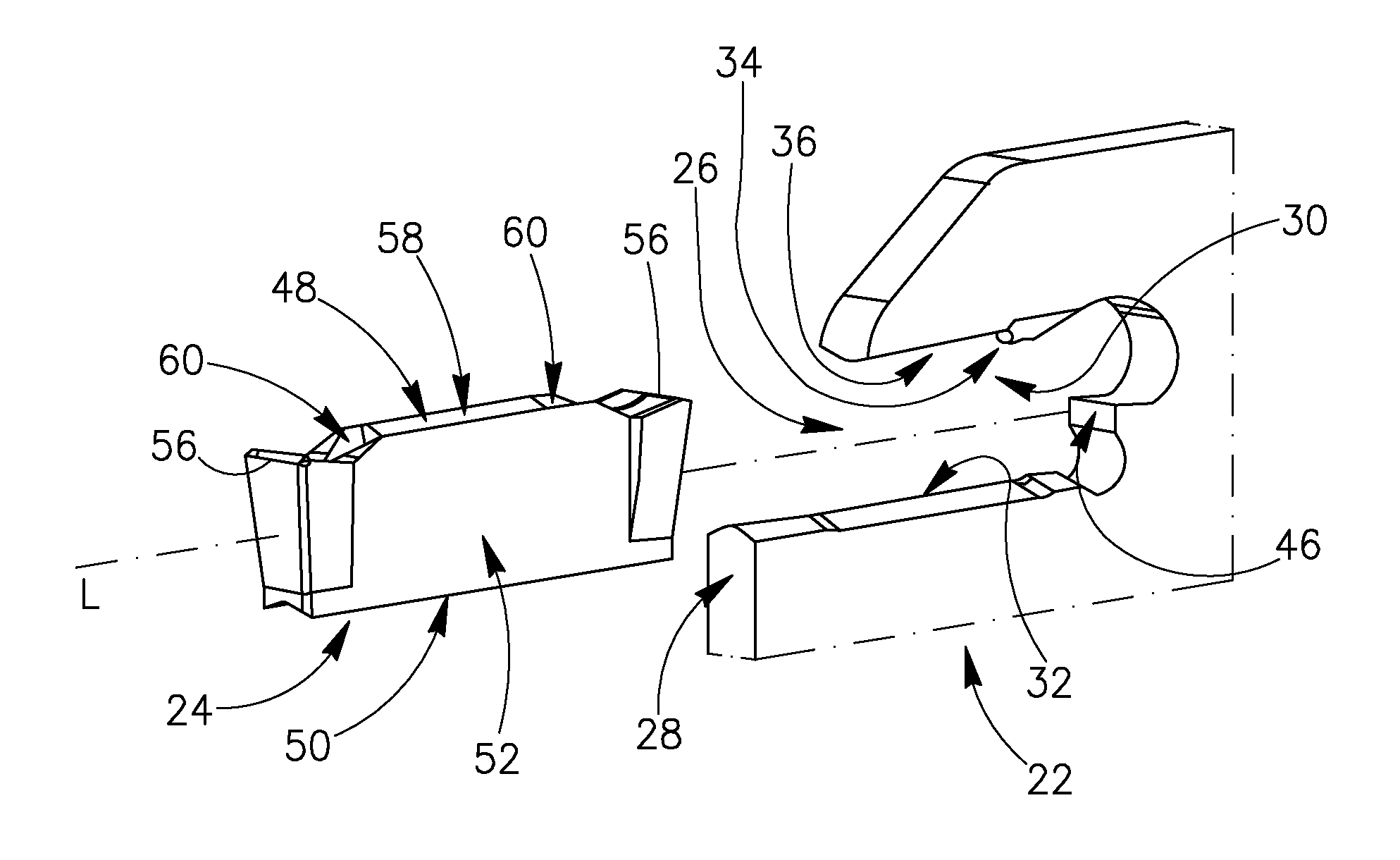
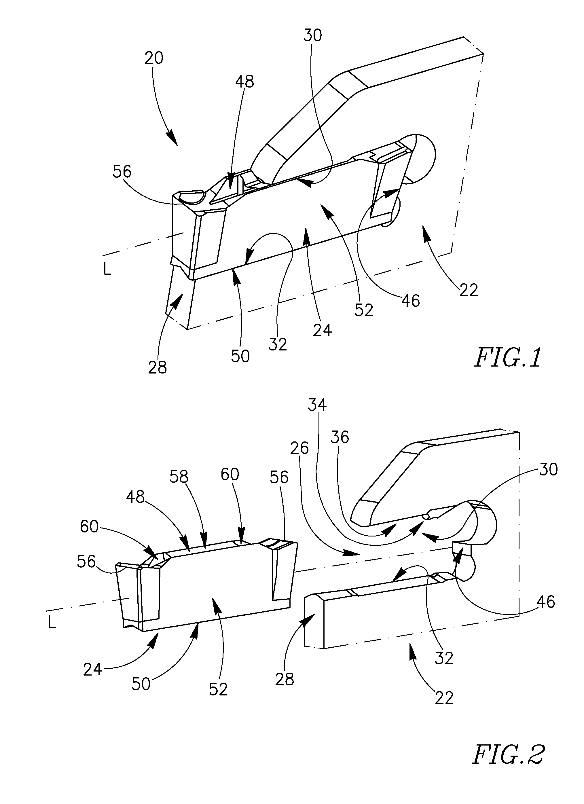
[0048]Attention is first drawn to FIGS. 1 and 2, showing a cutting tool 20 in accordance with some embodiments of the present invention, used for grooving and turning operations. The cutting tool 20 is in the form of a blade-shaped insert holder 22 manufactured from a first material and a cutting insert 24 manufactured from a second harder material, where the cutting insert 24 is removably secured in the insert holder 22 by means of self clamping. The cutting insert 24 may be manufactured by form pressing and sintering a carbide powder such as Tungsten Carbide.

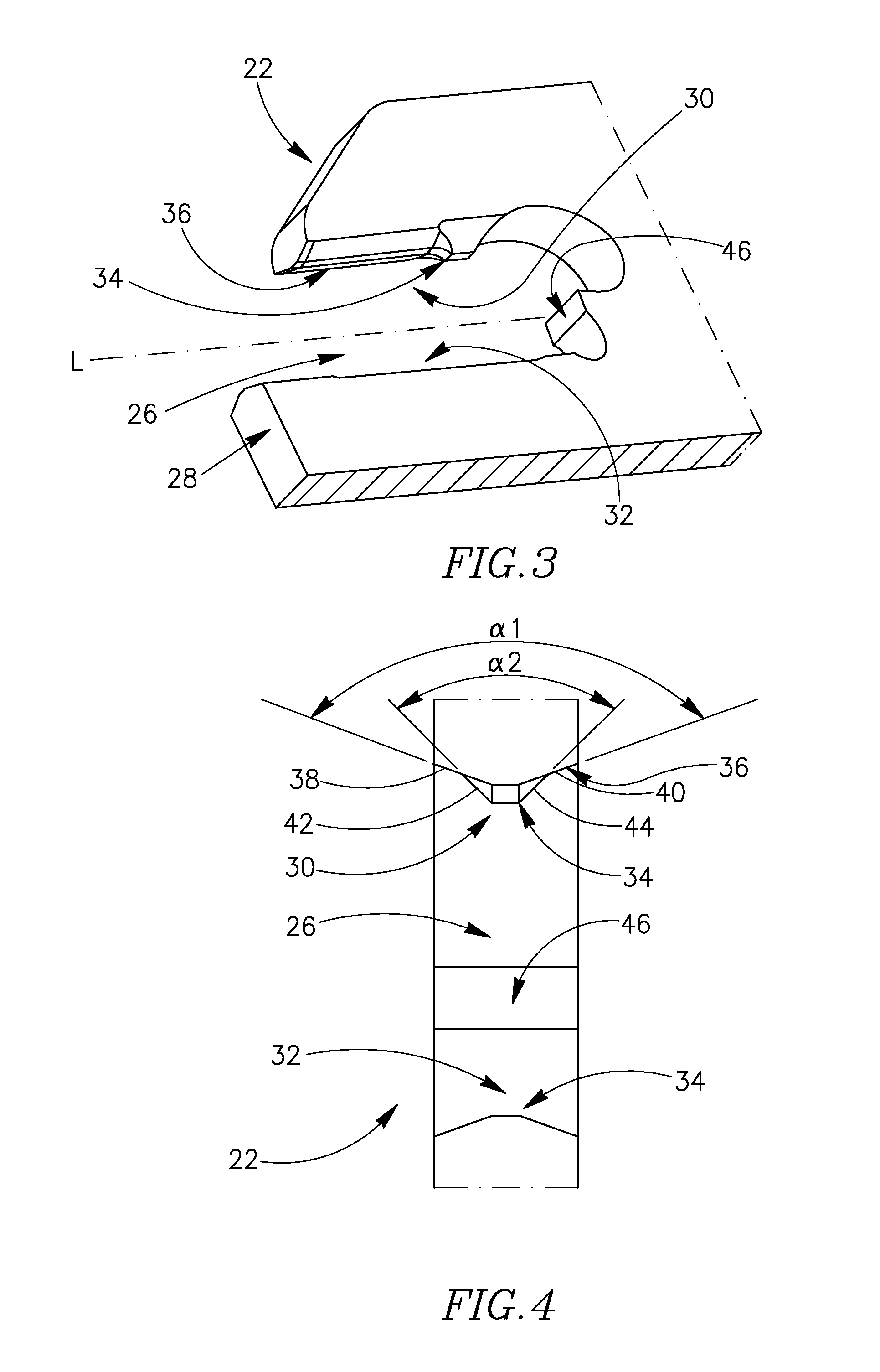
[0049]As shown in FIGS. 3 and 4, the insert holder 22 includes an insert receiving slot 26 opening out to a front end 28 of the insert holder 22 having upper and lower receiving slot surfaces 30, 32 extending in a common longitudinal direction L. The upper receiving slot surface 30 includes a single pair of lateral stopping surfaces 34 and a single pair of upper clamping surfaces 36 which are longitudinally separated and each ...


PUM

PropertyMeasurementUnit
angleaaaaaaaaaa
widthaaaaaaaaaa
contact distanceaaaaaaaaaa

Abstract

A cutting tool used for grooving and turning operations, where a cutting insert is removably securable in a blade-shaped insert holder. The insert holder includes an insert receiving slot having a longitudinally extending upper receiving slot surface with longitudinally separated single pairs of ridge type V-shaped lateral stopping and upper clamping surfaces, the planar surface components of which form different internal angles. The cutting insert includes an upper surface with a single pair of groove type V-shaped upper abutment surfaces longitudinally separated from two pairs of groove type V-shaped lateral abutment surfaces. Clamping contact occurs between the pairs of upper abutment and upper clamping surfaces, and lateral contact only occurs between one surface component of one of the two pairs of lateral abutment surfaces and one surface component of the pair of lateral stopping surfaces for cases of a sufficiently large side load on the cutting insert.

Description

FIELD OF THE INVENTION[0001]The present invention relates to a cutting tool and a cutting insert for use in metal cutting processes in general, and for grooving and turning operations in particular.BACKGROUND OF THE INVENTION[0002]Within the field of metal cutting tools used for grooving and turning operations, a cutting insert of typically small width and manufactured from a first material may be removably secured to a slotted portion of an insert holder having a similarly small width and manufactured from a second material, the first material being harder than the second material. Cutting forces are generally transmitted through the insert tip and the forward section of the insert holder lower surface, although in some grooving and turning operations a transverse component of the cutting force may initiate lateral displacement of the cutting insert with respect to the insert holder.[0003]U.S. Pat. No. 6,086,291 discloses a cutting tool for parting and grooving operations where the...

Claims


Application Information

Patent Timeline
Patent Type & Authority Applications(United States)
IPC IPC(8): B23B27/16B23B29/06
CPCB23B27/045B23B29/043B23C2210/161Y10T407/25Y10T407/22Y10T407/23B23B27/04B23B27/16B23B29/12
Inventor HECHT
Owner ISCAR LTD
Features
  • Generate Ideas
  • Intellectual Property
  • Life Sciences
  • Materials
  • Tech Scout
  • Unparalleled Data Quality
  • Higher Quality Content
  • 60% Fewer Hallucinations
Learn More