Motor drive device and electric equipment utilizing the same

a technology of motor drive and electric equipment, which is applied in the direction of motor/generator/converter stopper, electronic commutator, dynamo-electric converter control, etc., can solve problems such as unstable drive state, and achieve the effects of stable drive, extended driving range and high reliability

Inactive Publication Date: 2011-10-20
PANASONIC CORP
View PDF6 Cites 28 Cited by
  • Summary
  • Abstract
  • Description
  • Claims
  • Application Information

AI Technical Summary

Benefits of technology

[0011]Therefore, in the motor drive device of the present invention, even in drive at high speed/under high load, the drive is stable and a driving range i...

Problems solved by technology

Therefore, stable drive performance can be obtained when loa...

Method used


Image

  • Motor drive device and electric equipment utilizing the same
  • Motor drive device and electric equipment utilizing the same
  • Motor drive device and electric equipment utilizing the same

Examples


first exemplary embodiment

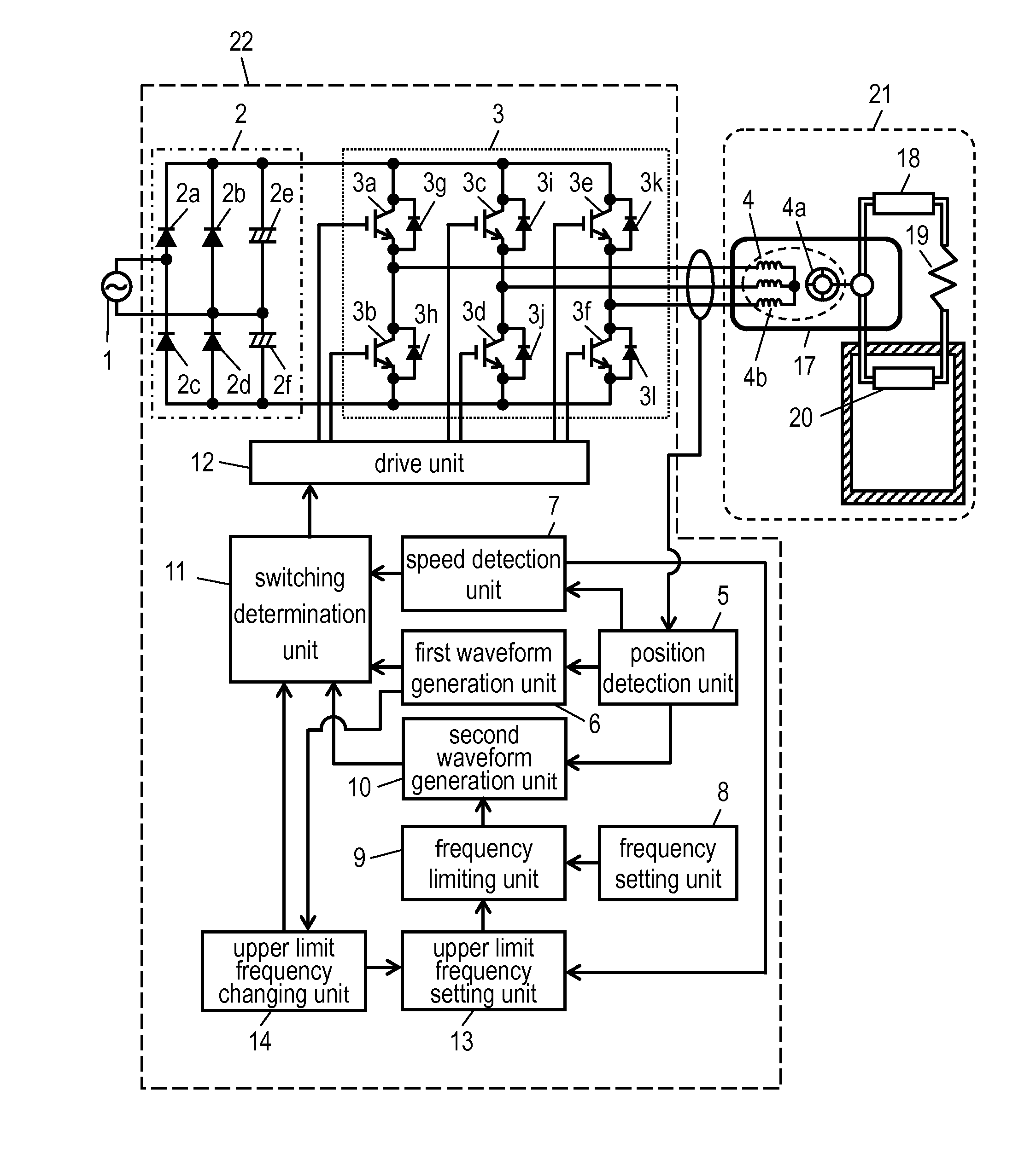
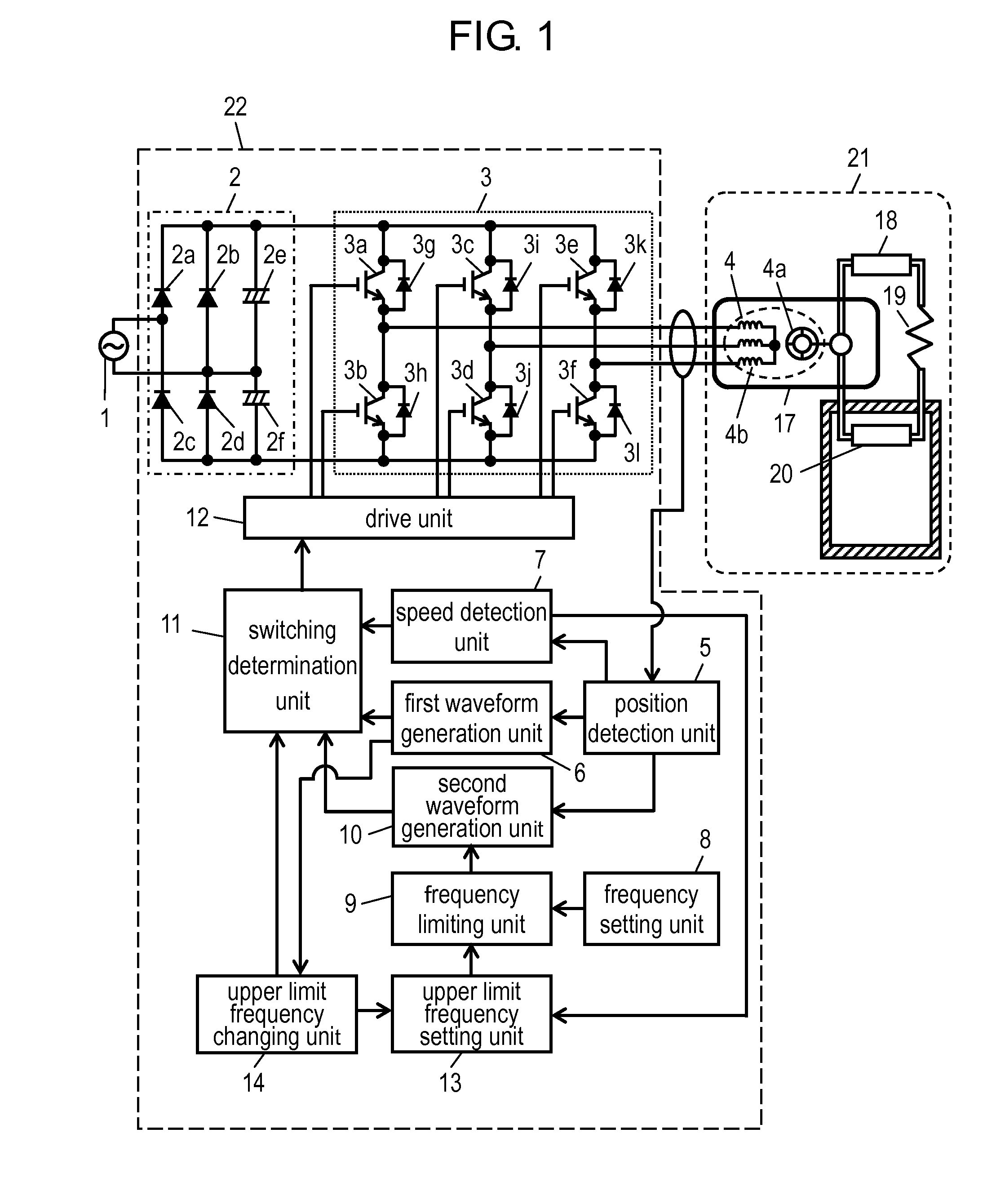
[0026]FIG. 1 is a block diagram showing a motor drive device in accordance with a first exemplary embodiment of the present invention. In FIG. 1, AC power supply 1 is a general commercial power supply. In Japan, it is a 50 Hz or 60 Hz power supply having an effective value of 100 V. Motor drive device 22 is connected to AC power supply 1 and drives brushless DC motor 4. Hereinafter, motor drive device 22 is described.

[0027]Rectifying and smoothing circuit 2 receives an input from AC power supply 1 and rectifies and smoothes AC electric power to DC electric power. Rectifying and smoothing circuit 2 includes four bridge-connected rectifier diodes 2a to 2d, and smoothing capacitors 2e and 2f. In this exemplary embodiment, rectifying and smoothing circuit 2 is made of a voltage doubler rectifying circuit, but rectifying and smoothing circuit 2 may be made of a full-wave rectifying circuit. Furthermore, in this exemplary embodiment, AC power supply 1 is a single-phase AC power supply. Ho...


PUM


Abstract

Brushless DC motor (4) is driven based on a first or second waveform signal output from switching determination unit (11), which switches outputting so that a first waveform signal by first waveform generation unit (6) is output when the speed of rotor (4a) is determined to be lower than a predetermined speed, and a second waveform signal by second waveform generation unit (10) is output when the speed of rotor (4a) is determined to be higher than the predetermined speed. Thereby, drive is stable even at high speed/under high load, and a driving range is extended.

Description

TECHNICAL FIELD[0001]The present invention relates to a motor drive device for driving a brushless DC motor and electric equipment using the same.BACKGROUND ART[0002]A conventional motor drive device drives a motor by switching between speed feedback drive and speed open-loop drive according to a current value or drive speed as disclosed in, for example, Patent Literature 1. FIG. 12 shows a conventional motor drive device described in Patent Literature 1.[0003]In FIG. 12, DC power supply 201 inputs DC power into inverter 202. Inverter 202 is configured by three-phase bridge connecting six switching elements. Inverter 202 converts the input DC power into AC power having a predetermined frequency, and inputs it into brushless DC motor 203.[0004]Position detection unit 204 obtains information on an induced voltage generated by the rotation of brushless DC motor 203 based on a voltage of an output terminal of inverter 202. Based on the information, position detection unit 204 detects a ...

Claims


Application Information

Patent Timeline
IPC IPC(8): F04B35/04H02P6/16F04B17/03H02P6/06F25B1/00H02P6/08H02P6/17
CPCH02P6/18F25B49/025H02P6/188H02P6/145F25B2600/021H02P6/153Y02B30/70
Inventor TAKEOKA, YOSHINORITANAKA, HIDEHISA
Owner PANASONIC CORP
Why Eureka
Try Eureka