Power control method, and power control apparatus

a power control and power storage device technology, applied in the direction of liquid/fluent solid measurement, process and machine control, instruments, etc., can solve the problem that the power storage device may not address a power demand increase which is much higher

Inactive Publication Date: 2011-10-20
FUJITSU LTD
View PDF12 Cites 15 Cited by
  • Summary
  • Abstract
  • Description
  • Claims
  • Application Information

AI Technical Summary

Benefits of technology

[0008]According to an aspect of the embodiments, a power control method for a power supplying unit for supplying power from a commercial power supply and a battery to a load, includes calculating a deviation amount between an actual power demand and a predicted power demand in a predetermined unit period on the basis of power demand transition data and power demand prediction data, the power demand transition data being stored in a power database, the power demand prediction data being stored in a prediction data storing unit, correcting, by a computer, a leveling target value on the basis of the calculated deviation amount, the leveling target value being a target value of power to be supplied from the commercial power supply, and controlling the power supplying unit so that the power supplying unit supplies power corresponding to the corrected leveling target value from the commercial power supply.

Problems solved by technology

However, according to this technology, the discharging from a power storage device may not address a power demand increase which is much higher than expected.

Method used


Image

  • Power control method, and power control apparatus
  • Power control method, and power control apparatus
  • Power control method, and power control apparatus

Examples


first embodiment

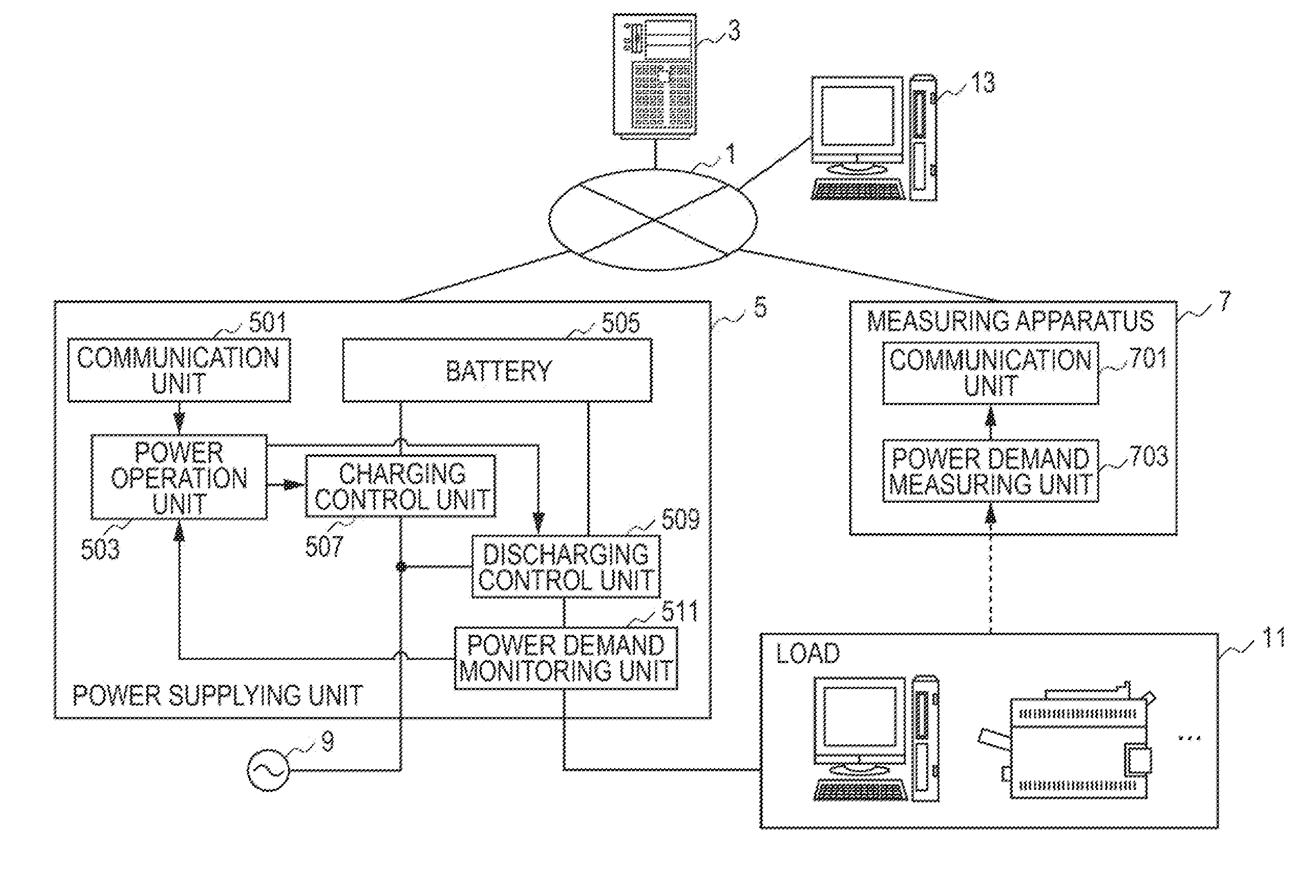
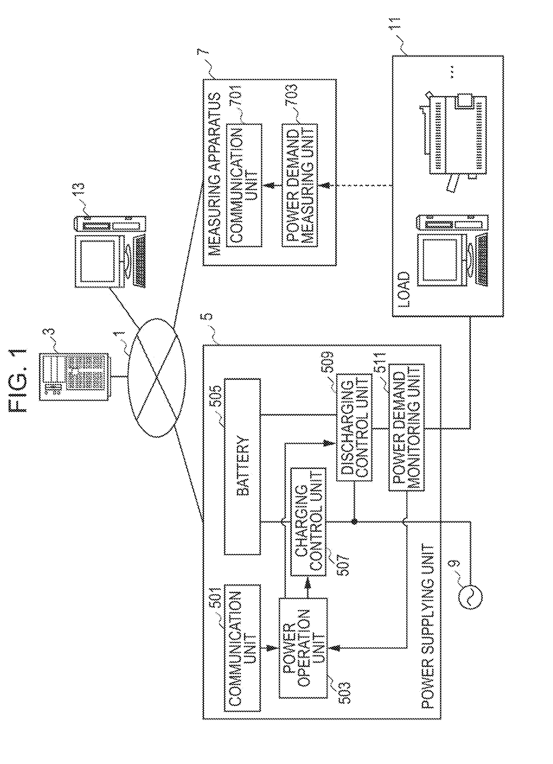
[0033]FIG. 1 is a configuration diagram of a system according to an embodiment. For example, to a network 1 which is an intra LAN (Local Area Network), a power management server 3, a power supplying unit 5, a measuring apparatus 7, and a management terminal 13 are connected. Furthermore, for example, a commercial power supply 9 which is a power receiving apparatus supplies power to the power supplying unit 5. The power supplying unit 5 may be an Uninterruptible Power Supply (UPS), for example, and may supply power to a load 11 which is an apparatus that consumes power, such as a personal computer, a printer, and a lighting, for example.

[0034]The power supplying unit 5 includes a communication unit 501, a power operation unit 503, a battery 505, a charging control unit 507, a discharging control unit 509, and a power demand monitoring unit 511.

[0035]The communication unit 501 performs processing including transmitting data on a remaining battery level to the power management server 3...

second embodiment

[0078]Next, a second embodiment will be described. According to the aforementioned first embodiment, the leveling desirable value is specified such that the peak value of the power supplied from a commercial power supply can be a minimum. According to the second embodiment on the other hand, the leveling desirable value is specified such that not only the peak value of the power supplied from a commercial power supply but also the amount of carbon dioxide exhausted by electric power generation can be reduced.

[0079]Since the configuration diagram of the system according to this embodiment and the function block diagram of the power management server 3 are the same as those described according to the first embodiment, the description will be omitted.

[0080]Next, with reference to FIG. 16 to FIG. 18, a leveling simulation (step S7) according to this embodiment will be described. First of all, with reference to FIG. 16, the concept of a leveling simulation according to this embodiment wi...

third embodiment

[0097]Next, a third embodiment will be described. According to the aforementioned first embodiment, the deviation between an actual power demand and a predicted power demand is monitored, and the leveling desirable value is corrected in accordance with the degree of deviation. On the other hand, according to this embodiment, the deviation between an actual remaining battery level and a predicted remaining battery level, and the leveling desirable value is corrected in accordance with the degree of deviation.

[0098]Since the configuration diagram of the system according to this embodiment and the function block diagram of the power management server 3 are the same as those described according to the first embodiment, the description will be omitted.

[0099]Next, with reference to FIG. 19 to FIG. 21, real time correction processing according to this embodiment will be described. The amount-of-correction calculating unit 3031 includes a calculation unit for calculating a deviation amount ...


PUM


Abstract

A power control method for a power supplying unit for supplying power from a commercial power supply and a battery to a load. The method includes (a) calculating a deviation amount between an actual power demand and a predicted power demand in a predetermined unit period on the basis of power demand transition data and power demand prediction data, (b) correcting, by a computer, a leveling target value on the basis of the calculated deviation amount, and (c) controlling the power supplying unit so that the power supplying unit supplies power corresponding to the corrected leveling target value from the commercial power supply. The power demand transition data is stored in a power database, and the power demand prediction data is stored in a prediction data storing unit. The leveling target value is a target value of power to be supplied from the commercial power supply.

Description

CROSS-REFERENCE TO RELATED APPLICATION[0001]This application is based upon and claims the benefit of priority of the prior Japanese Patent Application No. 2010-095154, filed on Apr. 16, 2010, the entire contents of which are incorporated herein by reference.FIELD[0002]The embodiments disclosed herein relate to technologies which control power to be supplied from a commercial power supply.BACKGROUND[0003]In recent years, many efforts have been made widely for suppressing a peak of a power load for power load leveling.[0004]Leveling a power load allows stable power supply from a power supplier (such as electric power company) and can eliminate the necessity for preparation of excessive electric power generation equipment costs for a power load peak. Shifting daytime power loads to the nighttime in which a lower proportion of power is generated by thermal power generation can reduce the amount of carbon dioxide exhausted when a unit amount of electricity is generated. On the other hand...

Claims


Application Information

Patent Timeline
Patent Type & Authority Applications(United States)
IPC IPC(8): G06F1/26
CPCG06F1/263G06F1/305G06F1/28
Inventor YAMAMOTO, HIROSHIUSHIKI, KAZUMASATSUNODA, TADANOBUFUJINO, NOBUTSUGU
Owner FUJITSU LTD
Why Eureka
Try Eureka