
Thermoacoustic engine

a technology of thermoacoustic engine and exhaust heat recovery, which is applied in the direction of machines/engines, mechanical equipment, lighting and heating apparatus, etc., can solve the problems of inability to efficiently recover the exhaust heat of conventional thermoacoustic engines, and the temperature of the exhaust heat is not constant, so as to achieve the effect of reducing the cost and simplifying the structure of the thermoacoustic engin

Inactive Publication Date: 2011-10-27
HONDA MOTOR CO LTD
View PDF8 Cites 16 Cited by
  • Summary
  • Abstract
  • Description
  • Claims
  • Application Information

AI Technical Summary

Benefits of technology

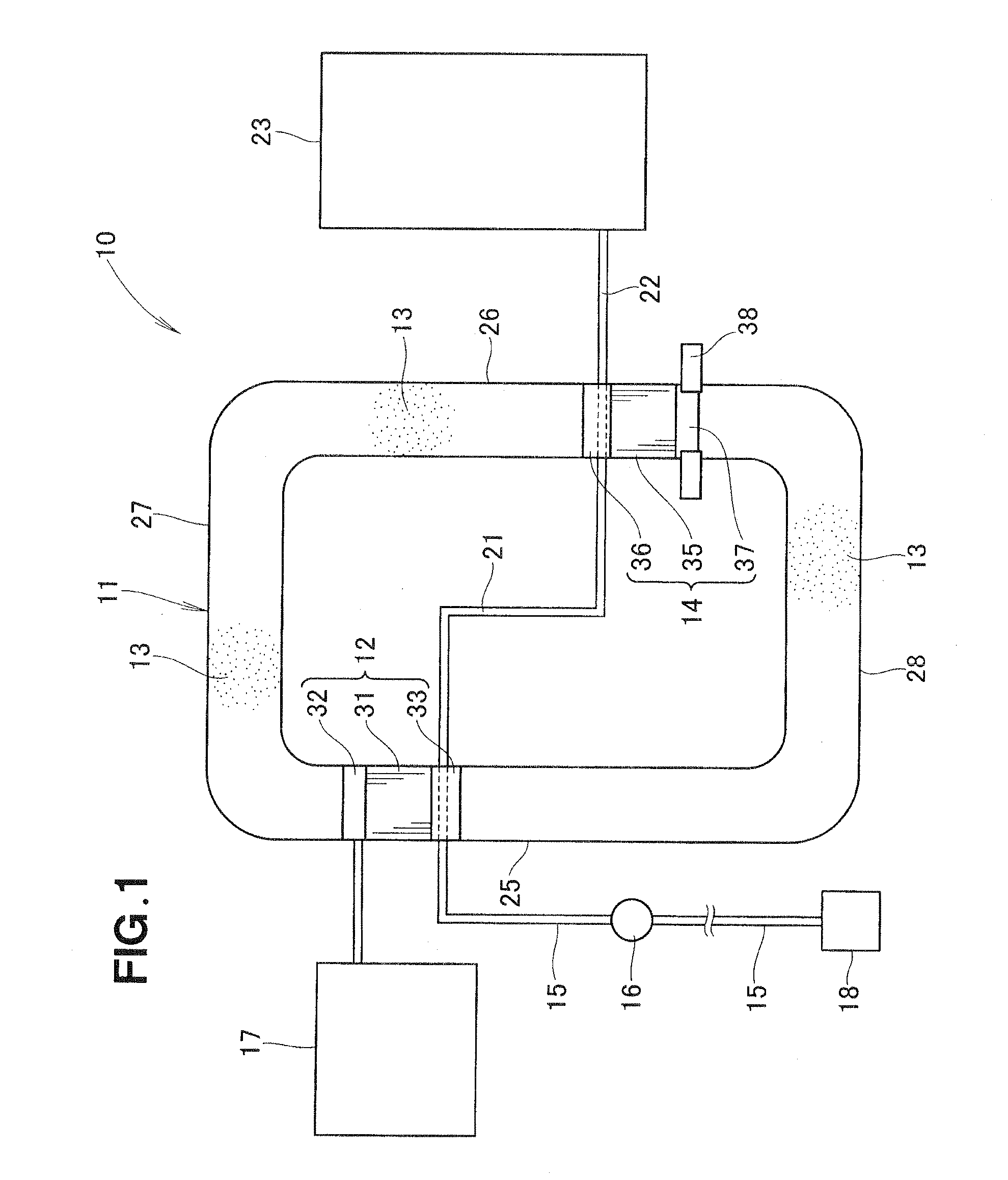
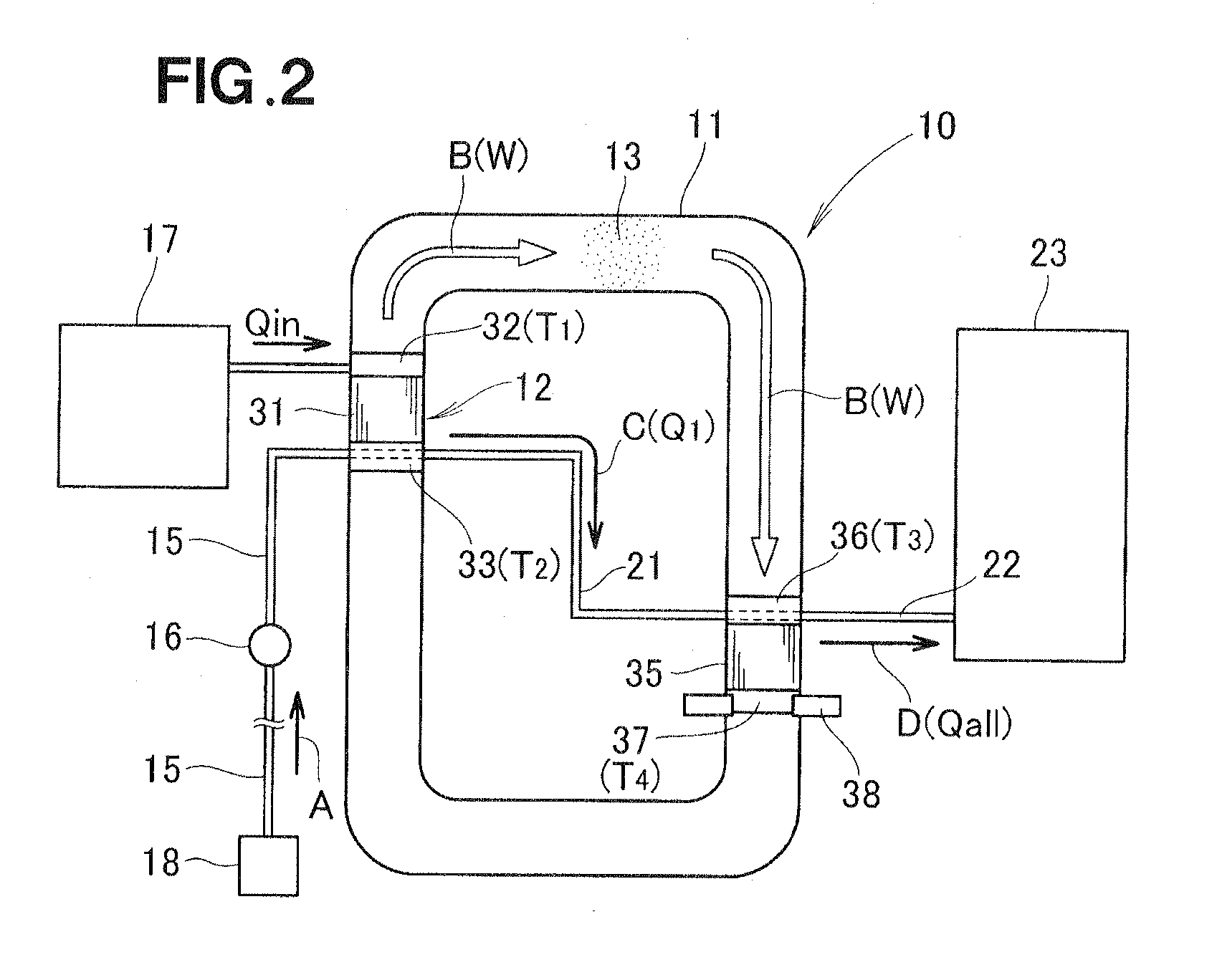
[0008]By virtue of the flow controller disposed on the cooling water passage, it is possible to adjust the flow rate of cooling water to be supplied to the second end of the first stack and the first end of the second stack in such a manner as to accommodate variations of the amount of heat of the hear source. With this flow rate control or adjustment, the heat of the heat source can be recovered with improved efficiency.
[0010]Preferably, the flow controller controls the flow rate of the cooling water such that the ratio of a temperature of the first end of the first stack to a temperature of the second end of the first stack is equal to the ratio of a temperature of the first end of the second stack and a temperature of the second end of the second stack. By thus controlling the temperature ratios of both ends of the first and second stacks, it is no longer necessary to keep the temperature of the first end (hot-side end) of the second stack at a constant value. This will allow for the use of a single device such as pump as the flow controller, achieving structural simplification and cost reduction of the thermoacoustic engine.

Problems solved by technology

However, such exhaust heats are not constant in temperature.
Furthermore, if the exhaust heat is near room temperature, efficient recovery of the exhaust heat by the conventional thermoacoustic engine is practically impossible.

Method used


Image

  • Thermoacoustic engine
  • Thermoacoustic engine
  • Thermoacoustic engine

Examples


Embodiment Construction

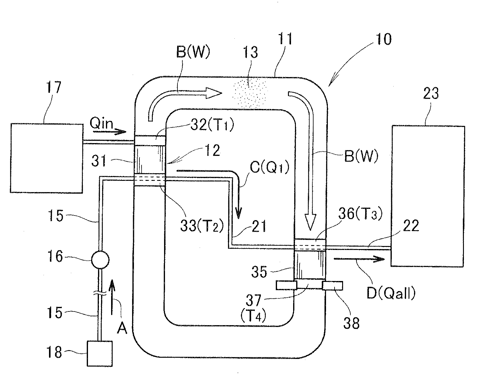
[0014]A thermoacoustic engine according to a preferred embodiment of the present invention will be described below with reference to FIG. 1. As shown in this figure, the thermoacoustic engine 10 takes the form of a looped tube type thermoacoustic engine and comprises an endless or looped tube 11 filled with a gas 13, a thermal acoustic generator 12 disposed in the looped tube 11 for inducing a sound wave upon application of external heat, a heat storage unit 14 disposed in the looped tube 11 for converting acoustic energy to heat energy to thereby recover heat upon injection of the sound wave propagating from the thermal acoustic generator 12, a cooling water passage 15 for guiding cooling water to the thermal acoustic generator 12, and a single flow control means or controller 16 disposed on the cooling water passage 15 for controlling flow rate of the cooling water. In the context of the claim language, the thermal acoustic generator 12 and the heat storage unit 14 may be also ref...


PUM


Abstract

A thermoacoustic engine includes a first stack and a second stack disposed in a gas-filled looped tube. The first stack has a first end to which heat is inputted and a second end to which cooling water is inputted, and the second stack has a first end to which the cooling water is inputted after passing through the second end of the first stack, and a second end provided with a cooling device. The thermoacoustic engine further includes a flow controller for controlling the flow rate of the cooling water to be inputted to the second end of the first stack.

Description

FIELD OF THE INVENTION[0001]The present invention relates to a thermoacoustic engine having two stacks embedded in a gas-filled looped tube such that heat inputted to the first stack is recovered by the second stack via sound power induced by the first stack and propagating to the second stack.BACKGROUND OF THE INVENTION[0002]Thermoacoustic engines are known as a device for recovering heat (exhaust heat) of a heat source. A typical example of such known thermoacoustic engines is disclosed in Japanese Patent Application Laid-Open Publication (JP-A) No. 2000-88378. The disclosed thermoacoustic engine includes a stack and a heat storage unit that are embedded in a gas-filled looped tube, and a hot-side heat exchanger and a cold-side heat exchanger that are disposed on opposite sides of each of the stack and the heat storage unit.[0003]In order to recover exhaust heat from a heat source, the hot-side heat exchanger associated with the stack is heated with heat supplied from the heat sou...

Claims


Application Information

Patent Timeline
Patent Type & Authority Applications(United States)
IPC IPC(8): F01B29/10
CPCF02G1/04F02G2243/54F25B7/00F25B9/145F01K23/10Y02P80/15
Inventor YAMAMOTO, YOSUKE
Owner HONDA MOTOR CO LTD
Learn More