Electrolysis apparatus

a technology for electrolysis apparatus and electrolysis chamber, which is applied in the field of electrolysis apparatus, can solve the problems of limited heat recovery mechanism and limited heat recovery mechanism, and achieve the effect of enhancing the pyroelectric

Inactive Publication Date: 2015-07-30
GAMIKON
View PDF11 Cites 9 Cited by
  • Summary
  • Abstract
  • Description
  • Claims
  • Application Information

AI Technical Summary

Benefits of technology

[0109]Typically electrodes are unevenly s

Problems solved by technology

However, the abovementioned arrangements do not describe electrolysis apparatus optimised for hydrogen and hea

Method used


Image

  • Electrolysis apparatus
  • Electrolysis apparatus
  • Electrolysis apparatus

Examples


Embodiment Construction

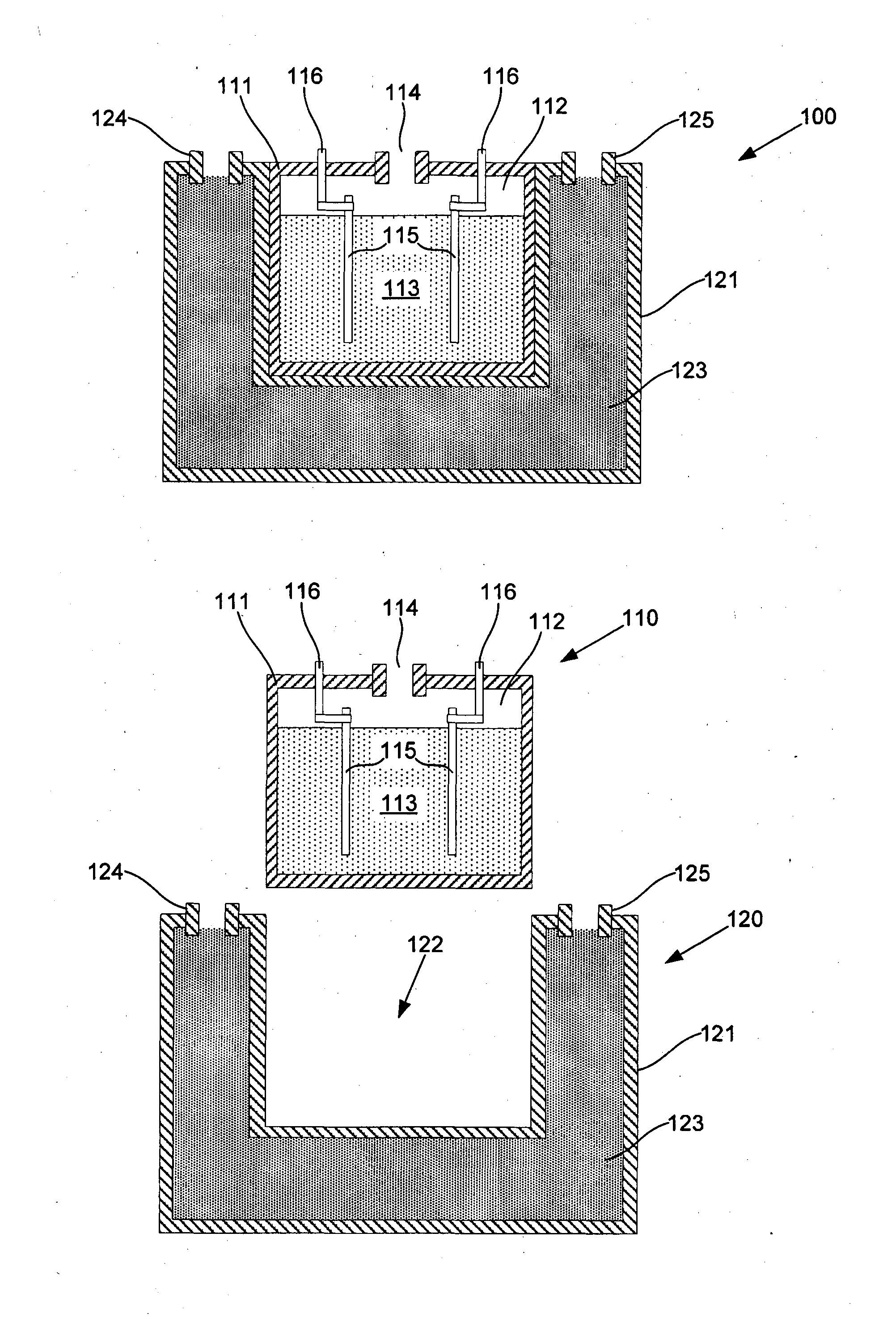
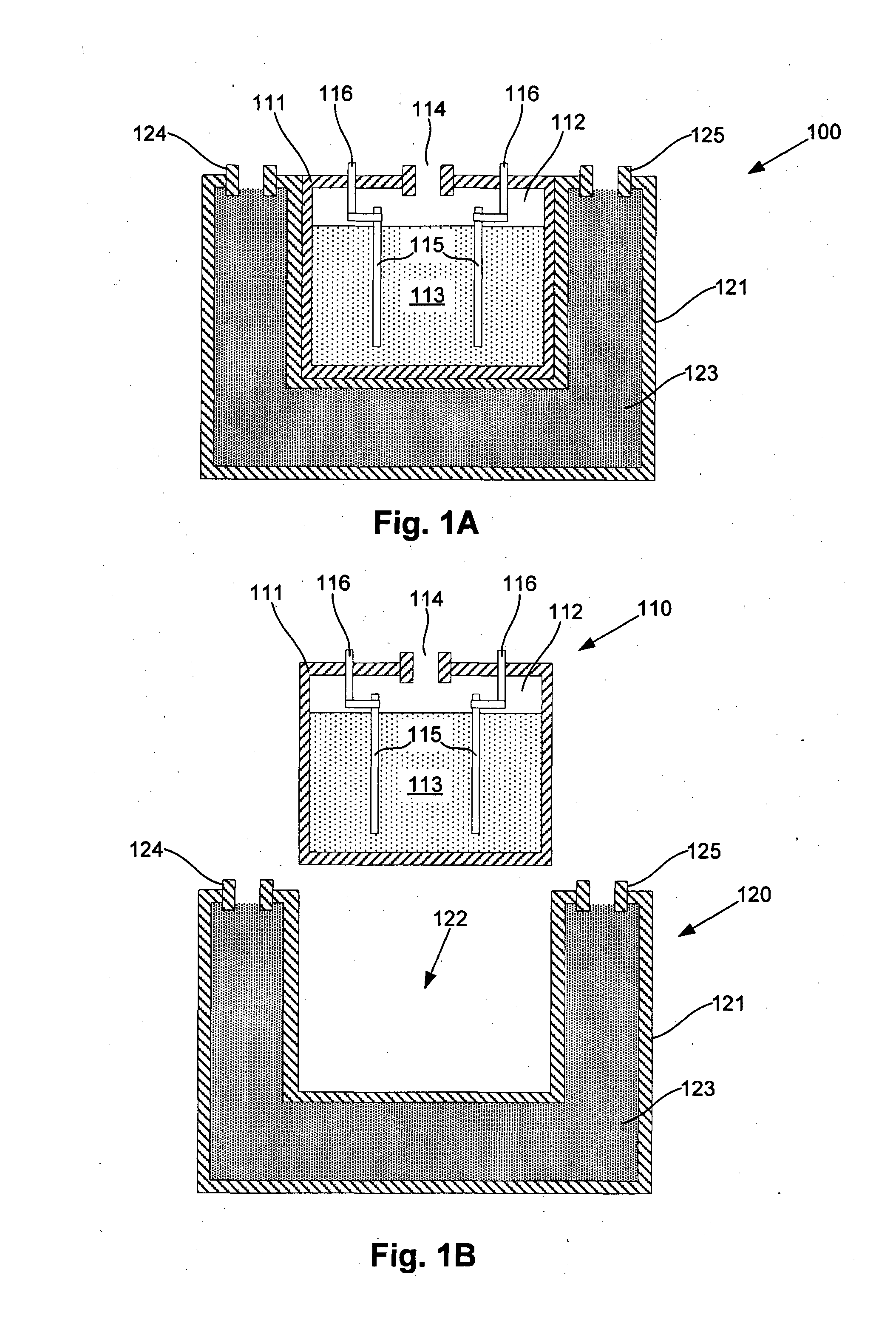
[0255]An example of apparatus for generating hydrogen and heat will now be described with reference to FIGS. 1A and 1B.

[0256]In this example, the apparatus 100 includes an electrolysis cell 110 and a heat recovery module 120. The electrolysis cell 110 includes a cell housing 111 defining an electrolyte cavity 112 containing an electrolyte 113 in use. The electrolyte cavity 112 is typically pressurised in use so that electrolysis is performed at a pressure greater than normal atmospheric pressure.

[0257]The electrolysis cell 110 further includes at least one cell outlet 114 in fluid communication with the electrolyte cavity 112, so that in use electrolysis products generated through electrolysis can be collected therefrom. A plurality of electrodes 115 is provided within the electrolyte cavity 112, the plurality of electrodes 115 defining at least one anode and at least one cathode. The electrodes 115 are connected to respective connectors 116, which are in turn connected to an electr...


PUM


Abstract

Apparatus for performing electrolysis and generating heat, the apparatus including an electrolysis cell including, a cell housing defining an electrolyte cavity, the electrolyte cavity containing an electrolyte in use, a plurality of substantially parallel spaced apart electrode plates provided within the electrolyte cavity, the electrode plates defining at least one anode and at least one cathode at least partially submersed within the electrolyte in use, at least two connectors, which in use are connected to an electrical power supply thereby allowing an electrical current to be supplied to the electrolyte to thereby perform electrolysis and heating of the electrolyte, at least one cell outlet in fluid communication with the electrolyte cavity, the at least one cell outlet being coupled to a heat recovery module in use and at least one cell inlet allowing electrolyte to be supplied to the electrolyte cavity.

Description

BACKGROUND OF THE INVENTION[0001]The present invention relates to an apparatus for performing electrolysis, and in one example for performing electrolysis of water for the generation of hydrogen and heat.DESCRIPTION OF THE PRIOR ART[0002]The reference in this specification to any prior publication (or information derived from it), or to any matter which is known, is not, and should not be taken as an acknowledgment or admission or any form of suggestion that the prior publication (or information derived from it) or known matter forms part of the common general knowledge in the field of endeavour to which this specification relates.[0003]It is known to perform electrolysis of water, for example to generate hydrogen and / or oxygen. This has been proposed for a number of different scenarios, such as for generating usable energy from variable power supplies such as renewable sources.[0004]For example, U.S. Pat. No. 7,188,478 describes a power generation system comprising a liquid-cooled ...

Claims


Application Information

Patent Timeline
IPC IPC(8): C25B1/06C25B15/08
CPCC25B15/08C25B1/06C25B1/04C25B15/02C25B9/73C25B11/00C25B9/05F25B23/006Y02E60/36Y02P20/10Y02P20/133
Inventor JACOBS, GIDEON JOHANNES
Owner GAMIKON
Why Eureka
Try Eureka