Heat Exchanger and Water Heater

a technology of heat exchanger and water heater, which is applied in the direction of indirect heat exchanger, air heater, light and heating apparatus, etc., can solve the problems of difficult to recover such latent heat and low heat exchange efficiency in the conventional structur

Inactive Publication Date: 2007-09-27
NORITZ CORP
View PDF5 Cites 9 Cited by
  • Summary
  • Abstract
  • Description
  • Claims
  • Application Information

AI Technical Summary

Benefits of technology

[0021] According to a second aspect of the present invention, there is provided a water heater comprising a burner and a heat exchanger for recovering heat from combustion gas generated by the burner. The heat exchanger comprises a housing including axially opposite ends formed with a burner opening and a combustion gas outlet, respectively, a heat-exchange coiled tube including a plurality of loops arranged in the housing along the axial direction via a plurality of clearances, a space surrounded by the coiled tube and having one end communicating with the burner opening, a partition for preventing combustion gas supplied from the burner into the space from directly flowing through another end of the space and for causing the combustion gas to flow to the clearances, and a combustion gas path formed around the coiled tube for guiding the combustion gas flowed thereto by passing through the clearances to the combustion gas outlet. The loops comprise a tube having a thickness in the axial direction and a width in a direction perpendicular to the axial direction, and the width is larger than the thickness.

Problems solved by technology

However, the above-described conventional structure has the following problems.
Therefore, the heat exchange efficiency is low in the conventional structure.
However, with the conventional structure, it is difficult to recover such latent heat.

Method used


Image

  • Heat Exchanger and Water Heater
  • Heat Exchanger and Water Heater
  • Heat Exchanger and Water Heater

Examples


Embodiment Construction

[0144] Preferred embodiments of the present invention will be described below in detail with reference to the accompanying drawings.

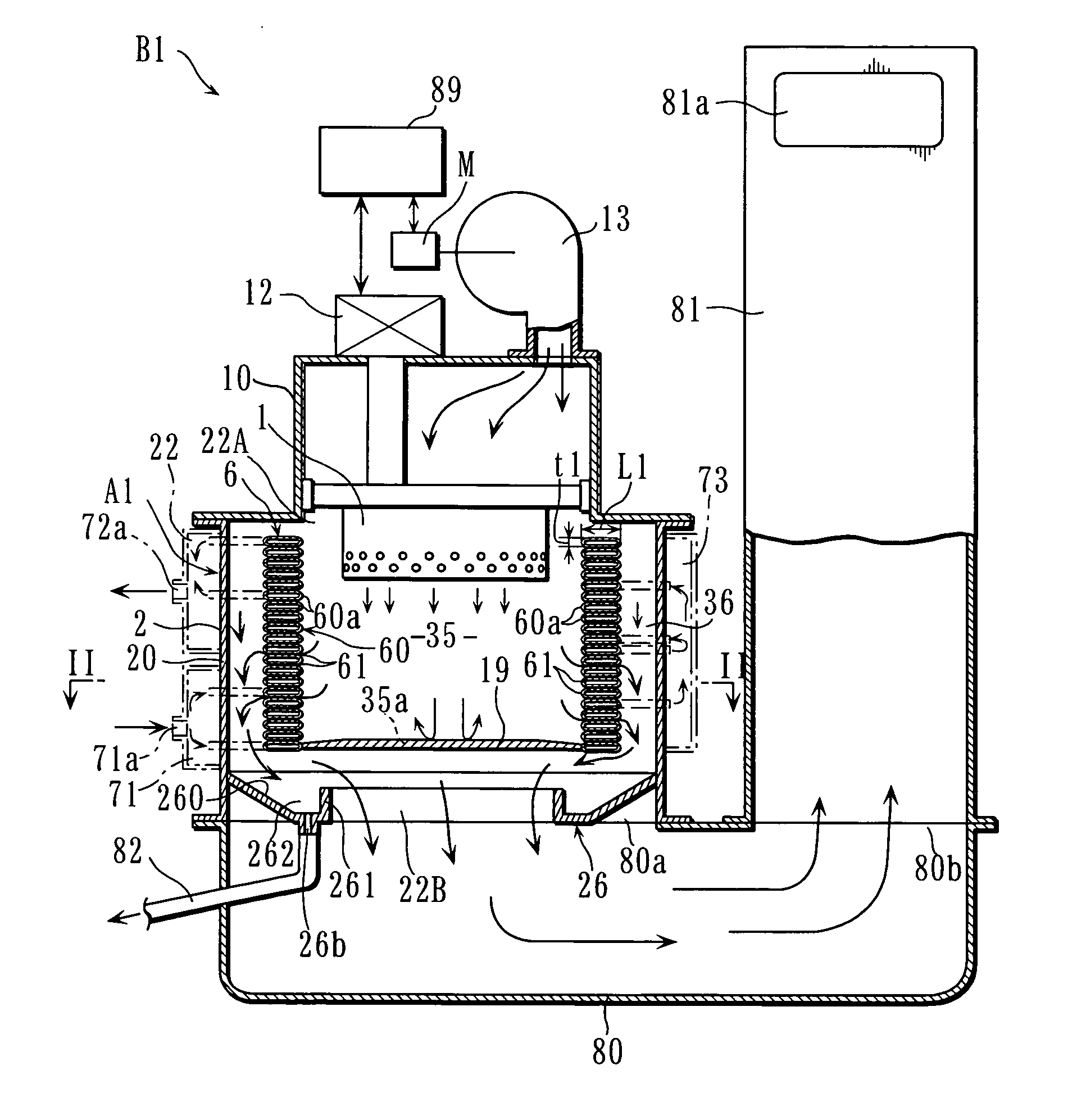
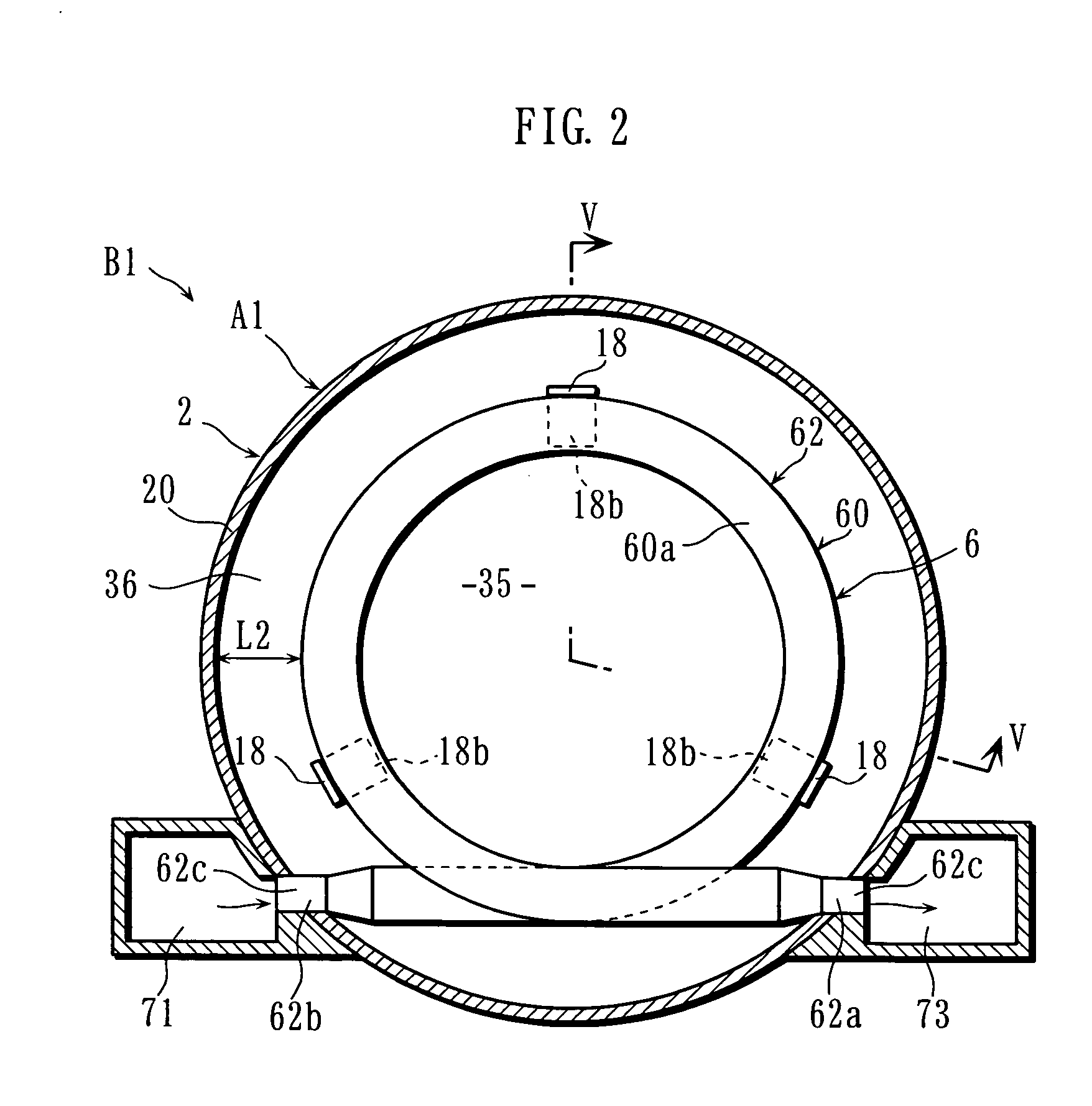
[0145]FIG. 1 shows an example of heat exchanger and water heater incorporating the heat exchanger according to the present invention. FIGS. 2-6 show the structure of the heat exchanger shown in FIG. 1 and the related parts thereof. As better shown in FIG. 1, the water heater B1 of this embodiment includes a burner 1, a bottom casing 80, an exhaust duct 81 and a controller 89 in addition to the heat exchanger A1.

[0146] The burner 1 is a reverse-combustion burner in which the gas obtained by vaporizing kerosene as the fuel is burned downward or kerosene is jetted downward for burning. On the heat exchanger A1, a housing 10 which is generally in the form of a box having an open bottom is placed. The burner 1 is arranged in and supported by the housing 10. A fan 13 for supplying air for combustion downwardly into the housing 10 is provided on the housing ...


PUM


Abstract

A heat exchanger A1 includes a coiled tube 60 including a plurality of loops 60a, and a space 35 surrounded by the coiled tube 60 and having an end closed by a partition 19. The heat exchanger is so designed that combustion gas flows from the space 35 to a combustion gas path 36 by passing through clearances 61 of the loops 60a of the coiled tube 60. The loops 60a are made of a tube having a thickness t1 and a width L1 which is larger than the thickness, so that the amount of heat recovery when the combustion gas passes through the clearances 61 is large. Therefore, the heat exchange efficiency is enhanced while simplifying the overall structure of the heat exchanger A1 and reducing the size of the heat exchanger.

Description

TECHNICAL FIELD [0001] The present invention relates to a heat exchanger for recovering heat from combustion gas and to a water heater incorporating a heat exchanger. BACKGROUND ART [0002] An example of heat exchanger is disclosed in Patent Document 1. As shown in FIG. 93, the heat exchanger disclosed in this document includes a heat exchange coiled tube 40e placed in a housing 2e. The bottom of the space 3e surrounded by the coiled tube 40e is closed by a partition 6e. In the heat exchanger, when combustion gas is introduced from the top of the housing 2e, the combustion gas flows out from the space 3e by passing through the clearances of the coiled tube 40e and is discharged to the outside through the bottom opening of the housing 2e. On the other hand, a medium is supplied to the coiled tube 40e through one end thereof, and the medium is heated by the combustion gas. The heated medium flows out of the coiled tube 40e through the other end thereof. [0003] With this structure, sinc...

Claims


Application Information

Patent Timeline
Patent Type & Authority Applications(United States)
IPC IPC(8): F24H9/00F24H1/43F24H1/52F24H8/00F28D7/02F28F1/02F28F9/013F28F9/04
CPCF24H1/43F28F2240/00F24H1/523F24H8/00F28D7/0033F28D7/0066F28D7/024F28D7/14F28F1/02F28F9/013F28F9/0246F28F13/08F28F2210/06Y02B30/102F24H1/52Y02B30/00
Inventor HAMADA, TETSUROUHARA, HITOSHIYOSHITOMI, HIDEAKIUEHARA, KOZOTAKASHIMA, HIROAKIASAKAWA, MITUFUKU
Owner NORITZ CORP
Why Eureka
Try Eureka