Sludge drying system

A sludge drying and treatment system technology, applied in the direction of sludge treatment, sludge treatment, biological sludge treatment, etc., can solve the problem of the reduction of sludge calorific value, the difficulty of leachate phosphorus removal process, and the increase of sludge The difficulty of follow-up disposal and other issues, to achieve the effect of heat recovery and uniform density

Active Publication Date: 2016-03-16
BEIJING SOUND ENVIRONMENTAL ENG +1
View PDF3 Cites 9 Cited by
  • Summary
  • Abstract
  • Description
  • Claims
  • Application Information

AI Technical Summary

Problems solved by technology

High-pressure diaphragm box-type filter press can reduce the moisture content of sludge to less than 50% of the landfill standard, but a large amount of quicklime and iron salt must be added, and the additives account for about 30% to 40% of the dry basis of sludge.
The purpose of sludge reduction is not really achieved, and the calorific value of sludge is further reduced, which increases the difficulty of subsequent sludge disposal. For example, the compacted layer of the landfill is arched due to methane accumulation, and the leachate phosphorus removal process is more difficult.

Method used


Image

  • Sludge drying system

Examples


specific Embodiment approach

[0013] The sludge drying treatment system of the present invention, its preferred embodiment is:

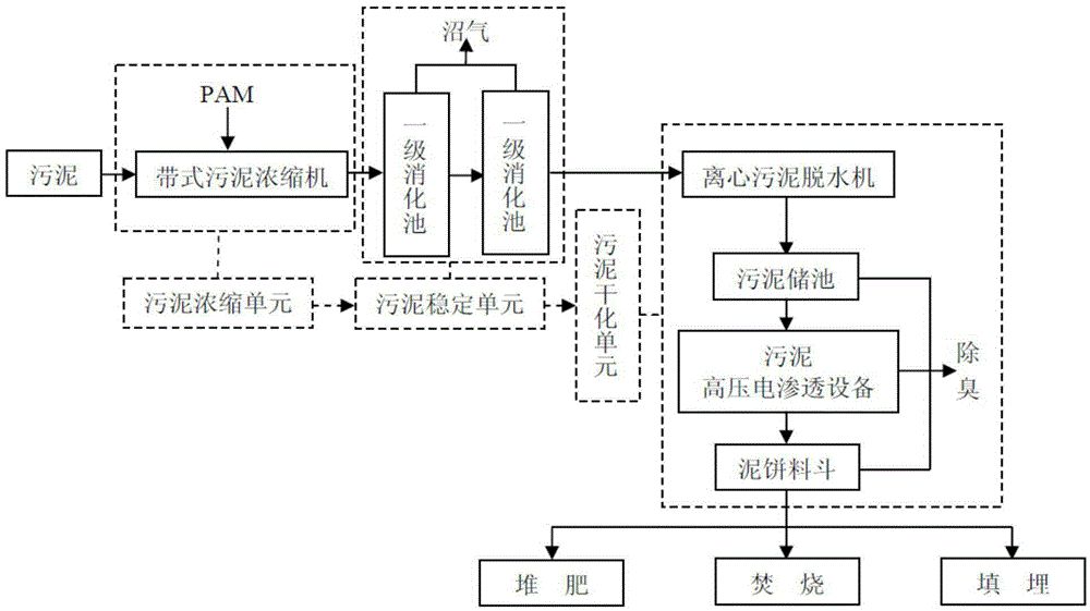
[0014] Including sludge thickening unit, sludge stabilization unit and sludge drying unit connected in sequence;

[0015] The sludge thickening unit includes a belt sludge thickener, and the belt sludge thickener is provided with a PAM dosing device;

[0016] The sludge stabilization unit is provided with a two-stage anaerobic digester for intermediate temperature sludge, and the anaerobic digester for intermediate temperature sludge is provided with a biogas outlet;

[0017] The sludge drying unit includes a sludge centrifugal dehydrator, a sludge storage tank, a sludge high-voltage electroosmosis equipment, and a mud cake hopper connected in sequence, and the sludge high-voltage electroosmosis equipment is provided with a deodorization device. The mud cake hopper is connected with a composting device, an incineration device and / or a landfill device.

[0018] The sludge high-v...

specific Embodiment

[0027] Such as figure 1 shown, including:

[0028] The sludge treatment system is composed of a sludge thickening unit, a sludge stabilization unit and a sludge drying unit connected in sequence.

[0029] The sludge concentration unit adopts a belt-type sludge thickener. During the concentration process, the dehydration performance of the sludge is improved by adding 1‰ to 5‰ of PAM, and the moisture content of the sludge is concentrated to 92% to 95%;

[0030] The sludge stabilization unit adopts two-stage anaerobic digestion of medium temperature sludge. The temperature is controlled between 34°C and 35°C, and the pH is adjusted by adding NaHCO 3 Control between 7-7.4;

[0031] For the anaerobic digestion of the two-stage medium-temperature sludge, the dosing rates of the primary digester and the secondary digester are controlled at about 5% and 15% respectively, and the digestion days are about 21d and 7d respectively;

[0032] The two-stage anaerobic digestion of mediu...


PUM

PropertyMeasurementUnit
heating valueaaaaaaaaaa

Abstract

The invention discloses a sludge drying system, comprising a sludge concentrating unit, a sludge stabilizing unit and a sludge drying unit which are connected in sequence, wherein the sludge concentrating unit comprises a belt sludge concentrator which is provided with a PAM adding device, the sludge stabilizing unit is provided with a medium-temperature sludge anaerobic digestion tank which is provided with a biogas outlet, the sludge drying unit comprises a sludge centrifugal dehydrator, a sludge storage tank, a sludge high-voltage electro-osmosis unit and a sludge cake hopper which are connected in sequence, the sludge high-voltage electro-osmosis unit is provided with a deodorizing device, and the sludge cake hopper is connected with a composting device, a burning device and/or a dumping device. The sludge drying system realizes quantitative reduction, harmlessness and recycling of sludge without addition of a reagent.

Description

technical field [0001] The invention relates to a sludge treatment technology, in particular to a sludge drying treatment system. Background technique [0002] With the continuous increase of the current sewage treatment rate, the output of sludge has shown a sharp upward trend, and the treatment and disposal of sludge has become the main factor restricting the development of many cities. Although most sewage treatment plants have concentrated and dewatered their sludge, the water content of the dewatered sludge after this simple concentrated dehydration treatment is usually still high, which makes the sludge treatment not in place, which not only increases the difficulty of transportation , and pose a threat to the surrounding environment of the transportation route, but what is more serious is that it brings great inconvenience to the subsequent sludge disposal: when composting, it cannot meet the moisture content requirements; when it is landfilled, it cannot reach the la...

Claims


Application Information

Patent Timeline
Patent Type & Authority Applications(China)
IPC IPC(8): C02F11/00C02F11/14C02F11/04C02F11/12C02F101/20
CPCC02F11/00C02F11/006C02F11/04C02F11/127C02F11/14C02F2101/20Y02E50/30Y02W10/20
Inventor 刘杰刘金泉王凯张小庆
Owner BEIJING SOUND ENVIRONMENTAL ENG
Why Eureka
Try Eureka