Flow control device

a flow control and flow control technology, applied in the direction of melt-holding vessels, mechanical devices, manufacturing tools, etc., can solve the problems of inability to accurately measure the passageway, small diameters are rendered moot, and the small width of the channel is prone to blockage, so as to increase the thermal conductivity of the device and the effect of high thermal conductivity

Inactive Publication Date: 2011-10-27
REFRACTORY INTELLECTUAL PRORERTY GMBH & CO KG
View PDF4 Cites 6 Cited by
  • Summary
  • Abstract
  • Description
  • Claims
  • Application Information

AI Technical Summary

Benefits of technology

[0045]An alternative solution conceived by the present Applicants to the problem of blockages in standard flow control devices (i.e. ones not including a wire according to the present invention), is to ensure that the body of the device has a higher thermal conductivity than normal, e.g. of at least 70 W/mK. A traditional device comprises approximately 99% alum

Problems solved by technology

Consequently, the problems associated with manufacturing devices with passageways having precise, small dia

Method used


Image

  • Flow control device
  • Flow control device
  • Flow control device

Examples


Embodiment Construction

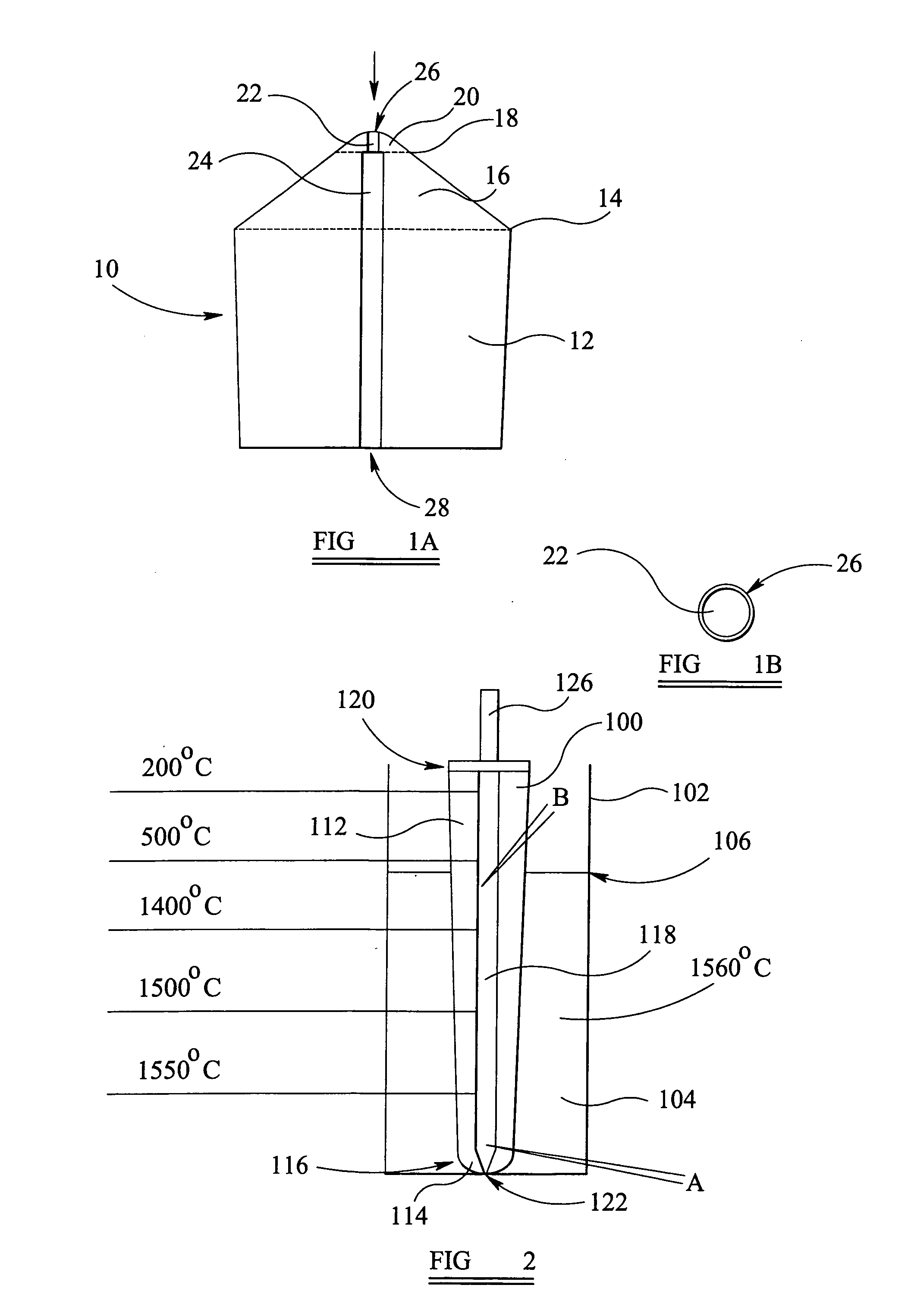
[0059]FIG. 1A shows a side cross-sectional view of a known flow control device 10 for use in a stopper rod 100 such as that shown in FIG. 2. The flow control device 10 comprises a frusto-conical body 12 that tapers slightly outwardly towards an upper end 14 of the body 12. At the upper end 14 a further frusto-conical section 16 is provided which tapers inwardly at approximately 45° to the horizontal. The frusto-conical section 16 has an upper terminating plane 18 of approximately a quarter the width of the upper end 14. A shallow rounded tip 20 extends upwardly from the plane 18. A narrow (1 mm diameter) cylindrical bore 22 is provided vertically through the centre of the tip 20. In the plane 18 the bore 22 is stepped to form a larger (3 mm diameter) cylindrical bore 24 that extends through the centre of the frusto-conical section 16 and the body 12. Accordingly, in this embodiment, an inlet 26 is provided at the upper end of the narrow bore 22 and an outlet 28 is provided at the lo...


PUM


Abstract

A flow control device (30) comprises a body (32) having an inlet (38), an outlet (40) and a passageway (36) therebetween. A wire (42) is positioned in the passageway (36) and a retaining means (44, 46) is provided for maintaining the wire (42) in the passageway (36).

Description

FIELD OF THE INVENTION[0001]This invention relates to a flow control device. Particularly, but not exclusively, the invention relates to a flow control device for use in a gas supply channel such as those employed in industrial processes, for example, in a continuous casting steel-making process.BACKGROUND TO THE INVENTION[0002]In a continuous casting steel-making process, molten steel is poured from a ladle into a large holding vessel known as a tundish. The tundish has one or more outlets through which the molten steel flows into one or more respective moulds. The molten steel cools and begins to solidify in the moulds to form continuously cast solid lengths of metal. A submerged entry nozzle is located between each tundish outlet and each mould, and guides molten steel flowing through it from the tundish to the mould. A stopper rod is often employed to control the flow rate of the molten steel through the submerged entry nozzle.[0003]The stopper rod generally comprises an elongat...

Claims


Application Information

Patent Timeline
IPC IPC(8): F16K25/00
CPCB22D41/16G05D7/01B22D41/186
Inventor NITZI, GERALDHEDLEY, TIMMCGUIRE, JOSEPHSTEVENSON, JOHN
Owner REFRACTORY INTELLECTUAL PRORERTY GMBH & CO KG
Why Eureka
Try Eureka