Power combiner/distributor and transmitter using the power combiner/distributor

a technology of power combiner and combiner, which is applied in the direction of electric/magnetic computing, instruments, computation using denominational number representation, etc., can solve the problems of loss of power absorbed by the termination resistor of the directional coupler connected to the terminal from which the failed amplifier has been removed, etc., to achieve the effect of minimizing the loss o

Active Publication Date: 2011-10-27
MITSUBISHI ELECTRIC CORP
View PDF4 Cites 9 Cited by
  • Summary
  • Abstract
  • Description
  • Claims
  • Application Information

AI Technical Summary

Benefits of technology

[0008]The present invention has been made to solve the above-mentioned problem, and an object to provide a power combiner / distributor that minimizes a distribution loss or a combination loss of the power combiner / distributor even if a part of a plurality of amplifiers fail when power is distributed to the plurality of amplifiers that operate in parallel, or when the powers from the plurality of amplifiers are combined together, and a transmitter using the power combiner / distributor.
[0013]According to the power combiner / distributor and the transmitter using the power combiner / distributor of the present invention, a connection line length between the stages is determined according to the number and length of impedance transformers disposed between the power combination points of the two connected branch circuits, and the power combiner / distributor is constituted by using such a connection line. As a result, when the electric power is distributed to the plurality of amplifiers that operate in parallel or when the electric powers from the plurality of amplifiers are combined together, the power combiner / distributor that minimizes the distribution loss or the combination loss thereof even if a part of the plurality of amplifiers fail, and the transmitter using the power combiner / distributor can be obtained.

Problems solved by technology

As a result, the distribution loss or the combination loss occurs in the power combiner / distributor.
However, the related art suffers from the following problem.
However, power absorbed by the termination resistor of the directional coupler connected to the terminal from which the failed amplifier has been removed is lost.
That is, the conventional power combiner / distributor suffers from such a problem that the power absorbed by at least the termination resistor is lost.

Method used


Image

  • Power combiner/distributor and transmitter using the power combiner/distributor
  • Power combiner/distributor and transmitter using the power combiner/distributor
  • Power combiner/distributor and transmitter using the power combiner/distributor

Examples


first embodiment

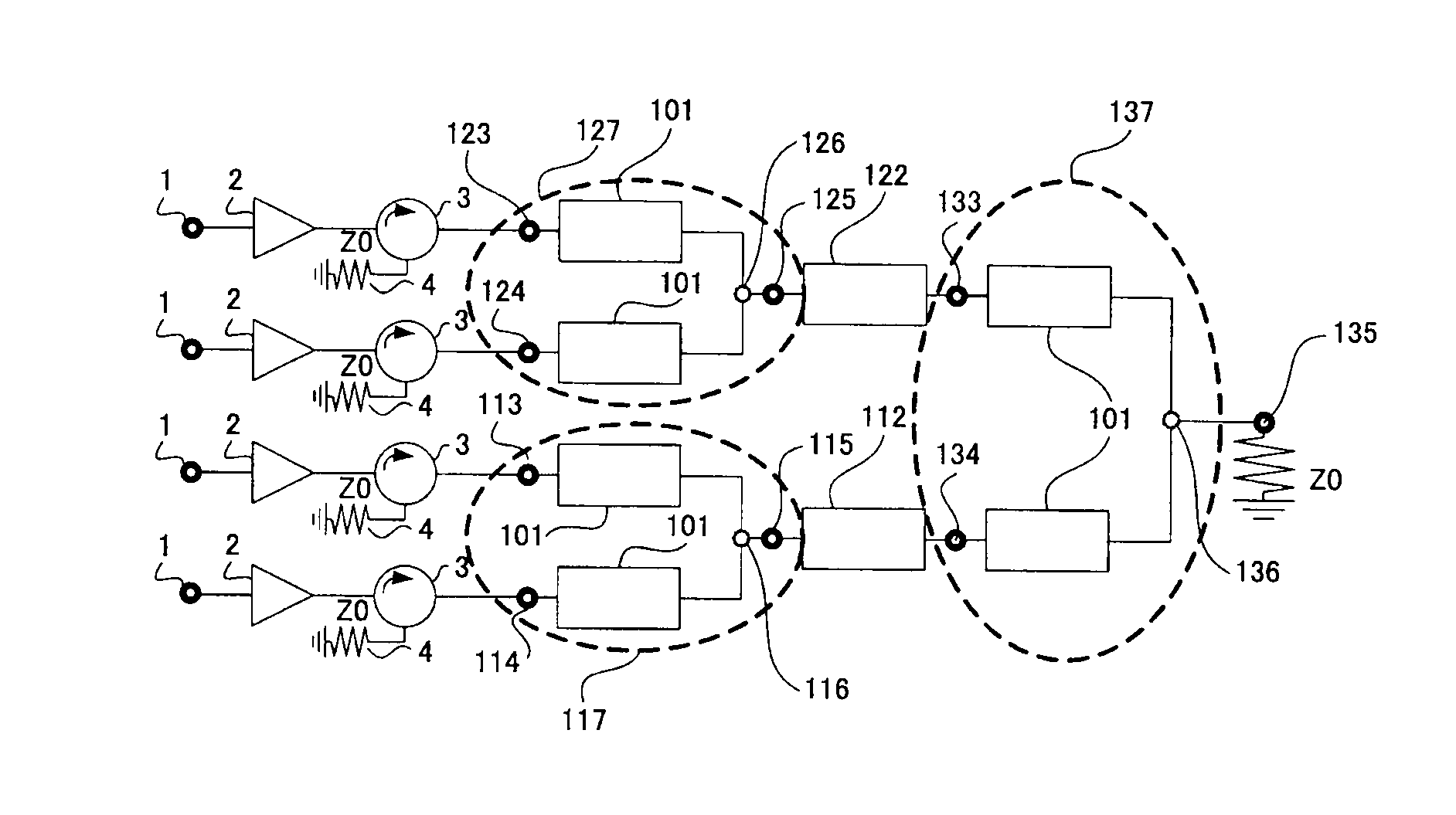
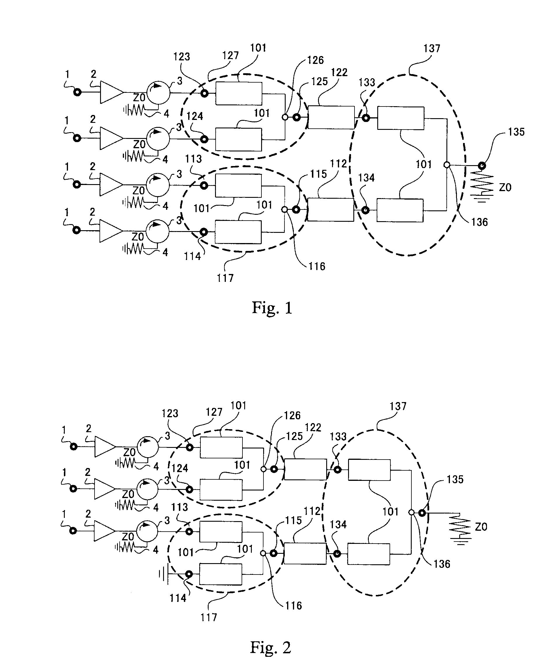
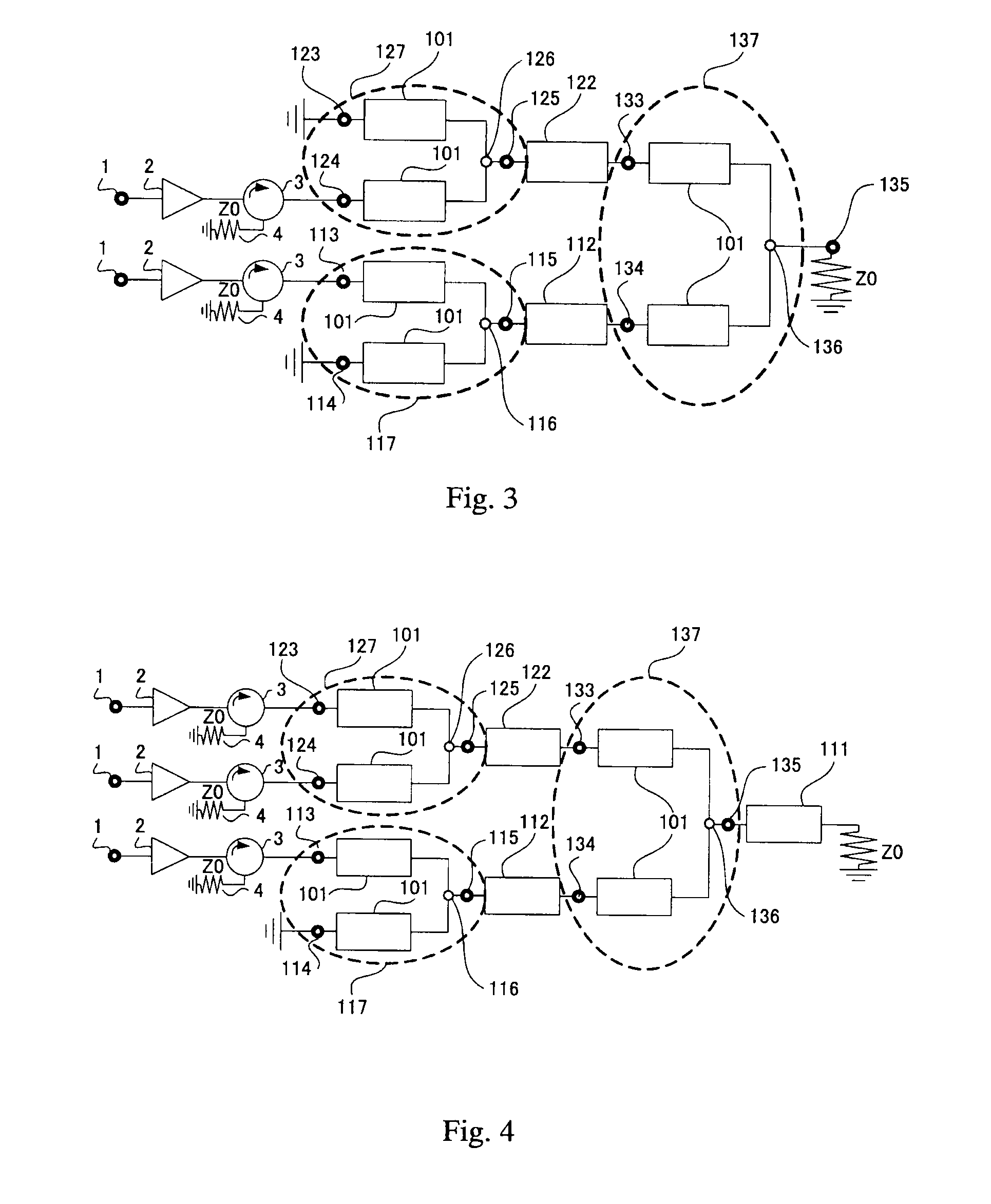
[0049]FIG. 1 is a circuit diagram of a power combiner according to a first embodiment of the present invention. The power combiner according to the first embodiment illustrated in FIG. 1 includes first impedance transformers 101, first connection lines 112 and 122, first branch side terminals 113, 114, 123, 124, 133, and 134, first combination side terminals 115, 125, and 135, and first power combination points 116, 126, and 136. Each of the first connection lines 112 and 122 has an electrical length equal to an odd multiple of about ¼ wavelength.

[0050]The power combiner / distributor illustrated in FIG. 1 has three first branch circuits 117, 127, and 137 (corresponding to portions indicated by dotted circles of FIG. 1), and the three first branch circuits 117, 127, and 137 are connected through the first connection lines 112 and 122 in a tournament fashion. The first branch circuit 117 includes the first impedance transformers 101, the first branch side terminals 113 and 114, the fir...

second embodiment

[0079]FIG. 5 is a circuit diagram of a power combiner according to a second embodiment of the present invention. The power combiner according to the second embodiment illustrated in FIG. 5 includes second impedance transformers 201, second connection lines 212 and 222, second branch side terminals 213, 214, 223, 224, 233, and 234, second combination side terminals 215, 225, and 235, and second power combination points 216, 226, and 236. Each of the second connection lines 212 and 222 has an electrical length equal to an odd multiple of about ¼ wavelength.

[0080]The power combiner / distributor illustrated in FIG. 5 has three second branch circuits 217, 227, and 237 (corresponding to portions indicated by dotted circles of FIG. 5), and the three second branch circuits 217, 227, and 237 are connected through the second connection lines 212 and 222 in a tournament fashion. The second branch circuit 217 includes the second impedance transformer 201, the second branch side terminals 213 and...

third embodiment

[0112]FIG. 9 is a circuit diagram of a power combiner according to a third embodiment of the present invention. The power combiner according to the third embodiment illustrated in FIG. 9 includes third connection lines 312 and 322, third branch side terminals 313, 314, 323, 324, 333, and 334, third combination side terminals 315, 325, and 335, and third power combination points 316, 326, and 336. Each of the third connection lines 312 and 322 has an electrical length equal to an integral multiple of about ½ wavelength.

[0113]The power combiner / distributor illustrated in FIG. 9 has three third branch circuits 317, 327, and 337 (corresponding to portions indicated by dotted circles of FIG. 9), and the three third branch circuits 317, 327, and 337 are connected through the third connection lines 312 and 322 in a tournament fashion. The third branch circuit 317 includes the third branch side terminals 313 and 314, the third combination side terminal 315, and the third power combination p...


PUM


Abstract

The power combiner / distributor for performing one of power combination and power division, includes: a first branch circuit (117) having a plurality of first branch side terminals (113, 114) connected in parallel and one first combination side terminal (115), which are connected through a first power combination point (116); and a second branch circuit (137) having a plurality of second branch side terminals (133, 134) connected in parallel and one second combination side terminal (135) connected through a second power combination point (136), the one first combination side terminal and the one of plurality of second branch side terminals being connected to each other, in which a length from the first power combination point to the second power combination point is an integral multiple of ½ wavelength.

Description

BACKGROUND OF THE INVENTION[0001]1. Field of the Invention[0002]The present invention relates to a power combiner / distributor used in a microwave band, and a transmitter using the power combiner / distributor, and more particularly, to a countermeasure to reduce a distribution loss or a combination loss.[0003]2. Description of the Related Art[0004]The power combiner / distributor has been widely used for combining or distributing power. In the case where the power is distributed and input to a plurality of amplifiers that operate in parallel, or in the case where the powers from the amplifiers are combined together, when a part of the amplifiers that operate in parallel fail, impedances at input / output terminals of the failed amplifier change. As a result, the distribution loss or the combination loss occurs in the power combiner / distributor.[0005]There is a method in which the power combiner / distributor is configured by a directional coupler in order to reduce such distribution loss or...

Claims


Application Information

Patent Timeline
Patent Type & Authority Applications(United States)
IPC IPC(8): G06G7/16H01P5/12H03F3/24H03F3/60H03F3/68H04B1/04
CPCH03F3/602H03F2203/21142H03F3/211H03F2203/21106H04B1/0483
Inventor HIROTA, AKIMICHITAHARA, YUKIHIROYONEDA, NAOFUMISAKAI, YUJI
Owner MITSUBISHI ELECTRIC CORP
Why Eureka
Try Eureka