Determining and displaying the 3D location and orientation of a cardiac-ablation balloon

a balloon catheter and location technology, applied in the field of medical fluoroscopy, can solve the problems that the electrodecardiologist performing such procedures has no good visualization method, and achieve the effect of improving visualization

Active Publication Date: 2018-11-08
APN HEALTH
View PDF0 Cites 3 Cited by
  • Summary
  • Abstract
  • Description
  • Claims
  • Application Information

AI Technical Summary

Benefits of technology

[0008]Another object of this invention is to provide such visualization in a manner which does not increase the length of time of the cardiac-ablation procedure.
[0010]Yet another object of this inventive method is to provide convenient and useful ways for the visualization to be displayed for the cardiologist, including ways in which the cardiologist may interact with the display device to enhance the insight provided.
[0027]The term “cardio-respiratory phase” as used herein refers to the phase of combined cardiac and respiratory motions. Therefore, as used herein, minimizing the difference between the cardio-respiratory phases of two images may also include minimizing a combination of measures of both cardiac phase and respiratory phase.
[0029]The term “3D balloon model” as used herein refers to a three-dimensional computer image of a cardiac-ablation balloon which includes shape and dimensional information corresponding to an actual cardiac-ablation balloon device. The shape and dimensional information may be customizable such that a “3D balloon model” is adaptable to represent more than one specific cardiac-ablation balloon device. The cardiologist may also adjust the color, opacity, and shading of the 3D model in order to enhance visualization.

Problems solved by technology

A major shortcoming in the use of cardiac-ablation technology has been that the electrocardiologist performing such procedures has had no good way to visualize after ablation has taken place just where the ablation has been applied.

Method used


Image

  • Determining and displaying the 3D location and orientation of a cardiac-ablation balloon
  • Determining and displaying the 3D location and orientation of a cardiac-ablation balloon
  • Determining and displaying the 3D location and orientation of a cardiac-ablation balloon

Examples


Embodiment Construction

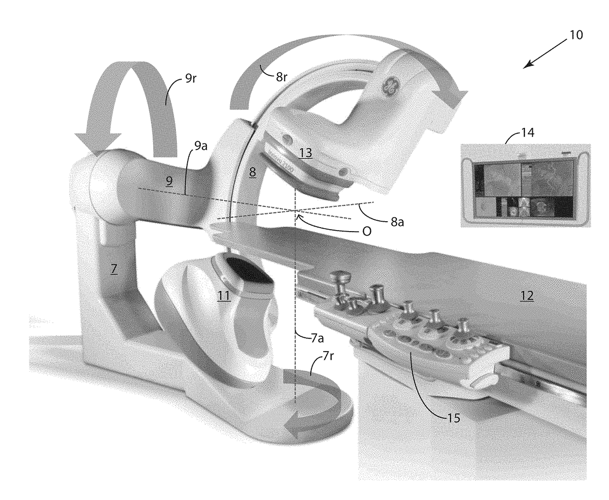
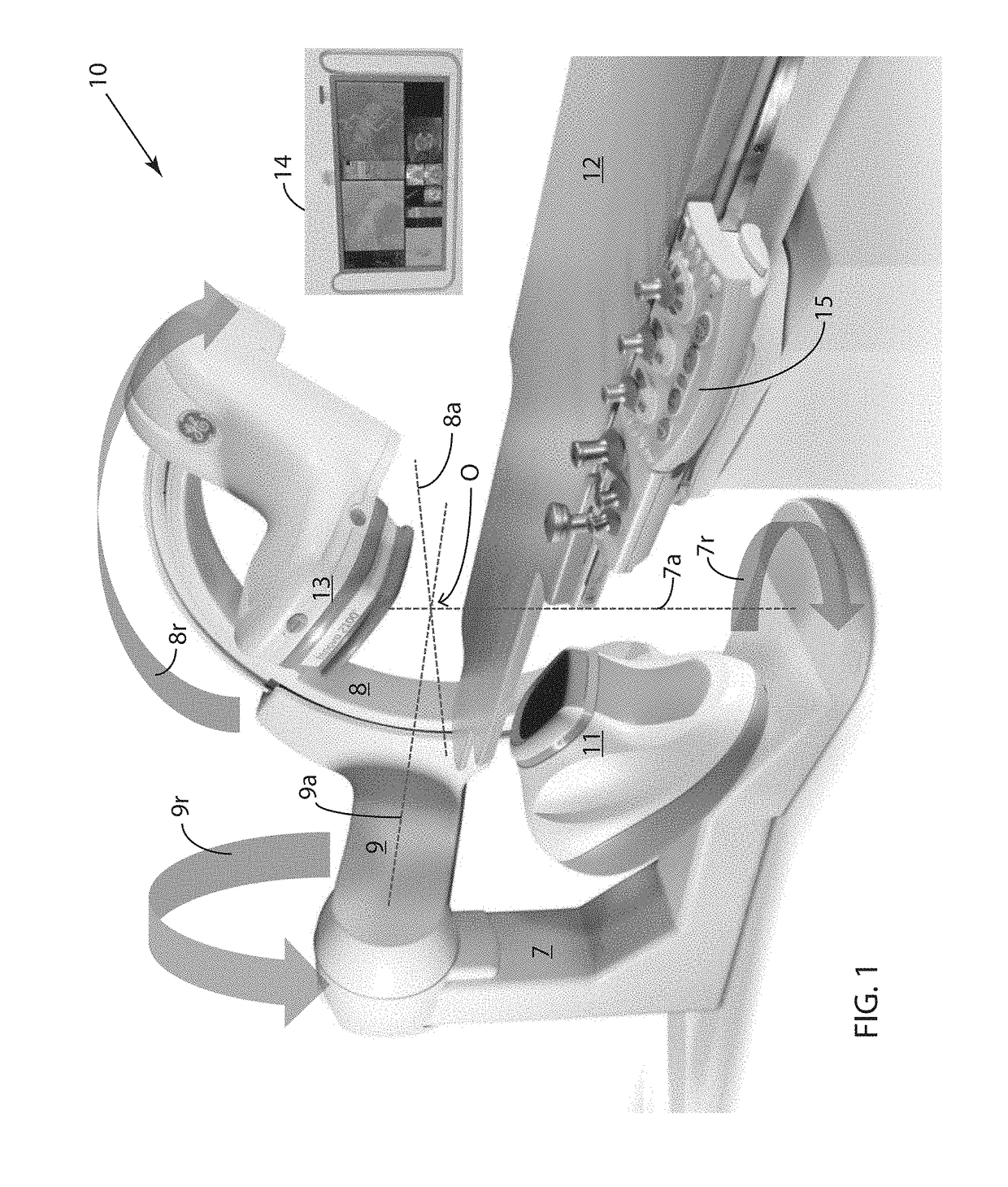
[0056]FIG. 1 illustrates an exemplary conventional fluoroscopic system 10 used to acquire 2D fluoroscopic image data. The imaging process for conventional fluoroscopy involves an X-ray source 11 which sends an X-ray beam through a patient (not shown) on a table 12. An X-ray detector 13, which may be a flat-panel detector or an image intensifier / video camera assembly, receives the X-rays transmitted through the patient and converts the X-ray energy into an image.

[0057]X-ray source 11 and X-ray detector 13 are mounted on opposite ends of a C-arm 8. Detector 13 may perform the conversion using an X-ray detection layer that either produces light or releases electrons when stimulated by X-rays, and a light-to-electron conversion layer, e.g., photodiodes or electron collection layer, as appropriate, in which an electrical charge signal proportional to X-ray signal intensity in each picture element (pixel) is collected. Analog-to-digital conversion then produces a digital image. Whatever t...


PUM


Abstract

A method for generating and displaying a 3D visualization of a cardiac-ablation balloon in a region of a living heart within a predefined 3D space, the method using single-plane fluoroscopic images and comprising: (1) placing, inflating and positioning the balloon into the region, the balloon having a radio-opaque location marker and central catheter portion; (2) capturing a burst of first-view digitized 2D images of the region from a fluoroscope positioned at a first angle; (3) capturing a burst of second-view digitized 2D images of the region from the fluoroscope positioned at a second angle different from the first angle; (4) selecting first-view and second-view images from the bursts such that the difference between measures of the cardio-respiratory phases of the selected first-view and second-view images is minimized; (5) identifying the location marker in each of the two selected images; (6) placing first and second orientation markers in the selected first-view and second view images, respectively, where the central catheter portion intersects the projected image of the inflated balloon at a farthest point from the location marker; (7) associating the location marker and the second orientation marker in the selected second-view image with the location marker and first orientation marker in the selected first-view image; (8) determining 3D location and orientation of the balloon in the region using the selected first-view and second-view images; (9) based on the determined location and orientation, inserting a 3D balloon model into the predefined space to generate the 3D visualization; and (10) displaying the 3D visualization on a display device, whereby a user can visualize where cardiac ablation was applied within the region.

Description

FIELD OF THE INVENTION[0001]This invention is related generally to the field of medical fluoroscopy, and more particularly to the area of cardioablation using a balloon catheter within a living heart.BACKGROUND OF THE INVENTION[0002]In recent years, wide-area ablation of cardiac tissue using balloons has been developed as an alternative to point-by-point ablation procedures. Several types of cardiac-ablation balloon catheters have been introduced. Among these are cryoballoons which use freezing (sometimes referred to as cryo energy) to ablate tissue, radio-frequency hot balloons which use radio-frequency energy for ablation, ultrasonic balloons which deliver focused ultrasonic energy to the tissue, and laser balloons which use light energy as the means of ablation.[0003]The use of cardiac-ablation balloon catheters for the treatment of patients with atrial fibrillation has become an important medical procedure such that it is estimated that in 2016, there were more than 80,000 such ...

Claims


Application Information

Patent Timeline
Patent Type & Authority Applications(United States)
IPC IPC(8): A61B6/12A61B6/00A61B18/14A61B18/24A61B5/0205A61B5/0456A61M25/10A61B5/352
CPCA61B6/12A61B2090/3966A61B6/487A61B18/1492A61B18/24A61B6/5288A61B5/0205A61B5/0456A61M25/10A61B2018/0022A61B2018/00357A61B2018/00577A61B2018/00994A61B2018/0212A61B5/08A61M2025/1079A61B6/466A61B18/02A61B2018/00351A61B2090/376A61B2034/104A61B2017/00699A61B2017/00703A61B2090/367A61B90/36
Inventor SRA, JASBIRKOHUT, SHIVANI
Owner APN HEALTH
Why Eureka
Try Eureka