
Ground-referenced common-mode amplifier circuit and related method

a common-mode amplifier and ground-reference technology, applied in the field of electrical circuits and systems, can solve the problems of inefficient or difficult to package many power amplifier configurations, and substantially increase the system cos

Active Publication Date: 2011-10-27
AVAGO TECH INT SALES PTE LTD
View PDF3 Cites 17 Cited by
  • Summary
  • Abstract
  • Description
  • Claims
  • Application Information

AI Technical Summary

Benefits of technology

[0007]The present invention is directed to a ground-referenced common-mode amplifier circuit and related method, substan...

Problems solved by technology

Unfortunately many power amplifier configurations are either inefficient or difficult to package.
That mitigating circuitry may take the form of one or more large blocking capacitors, for example, which occupy printed circuit board (PCB) area and may substantially increase system cost.

Method used


Image

  • Ground-referenced common-mode amplifier circuit and related method
  • Ground-referenced common-mode amplifier circuit and related method
  • Ground-referenced common-mode amplifier circuit and related method

Examples


Embodiment Construction

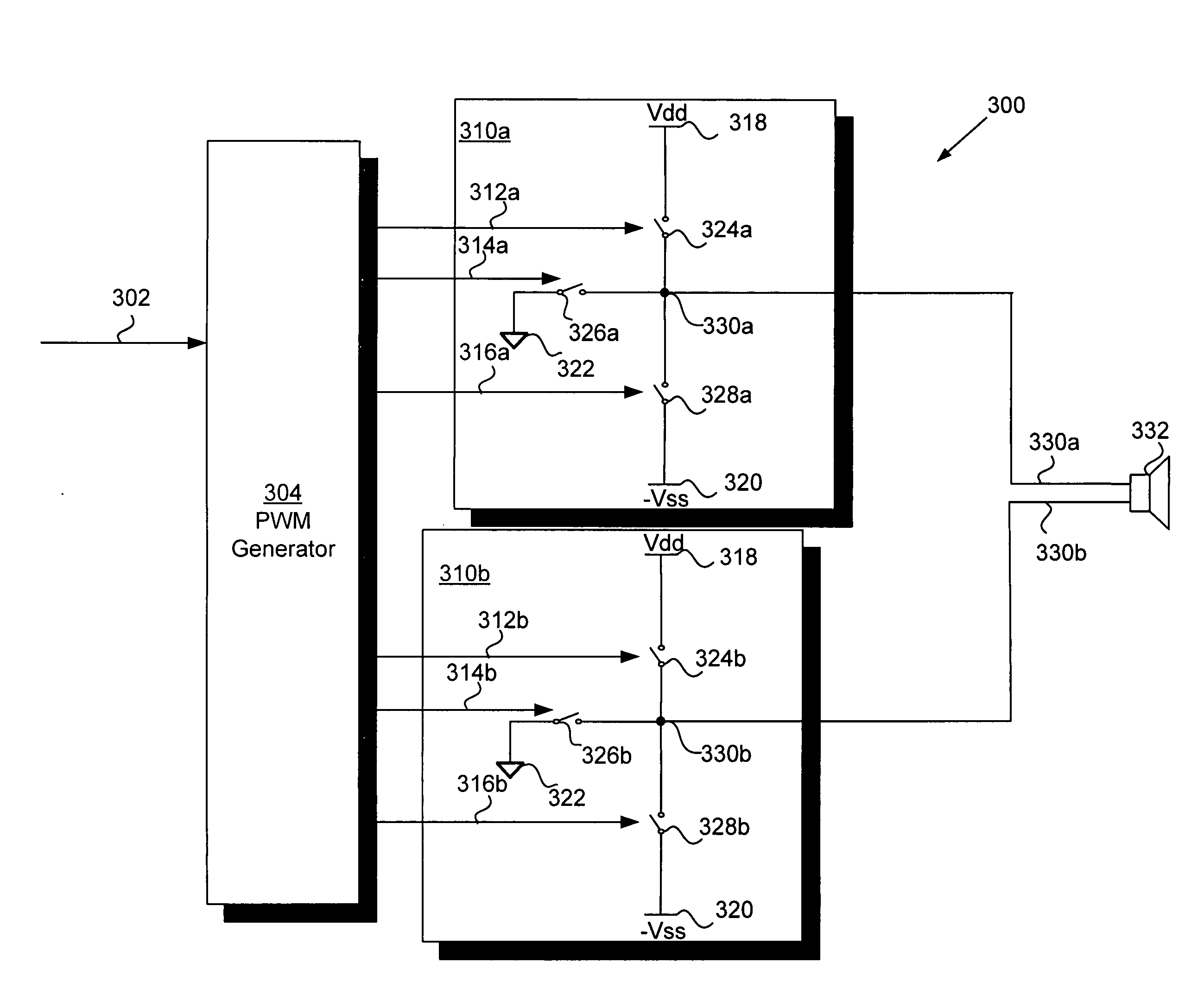
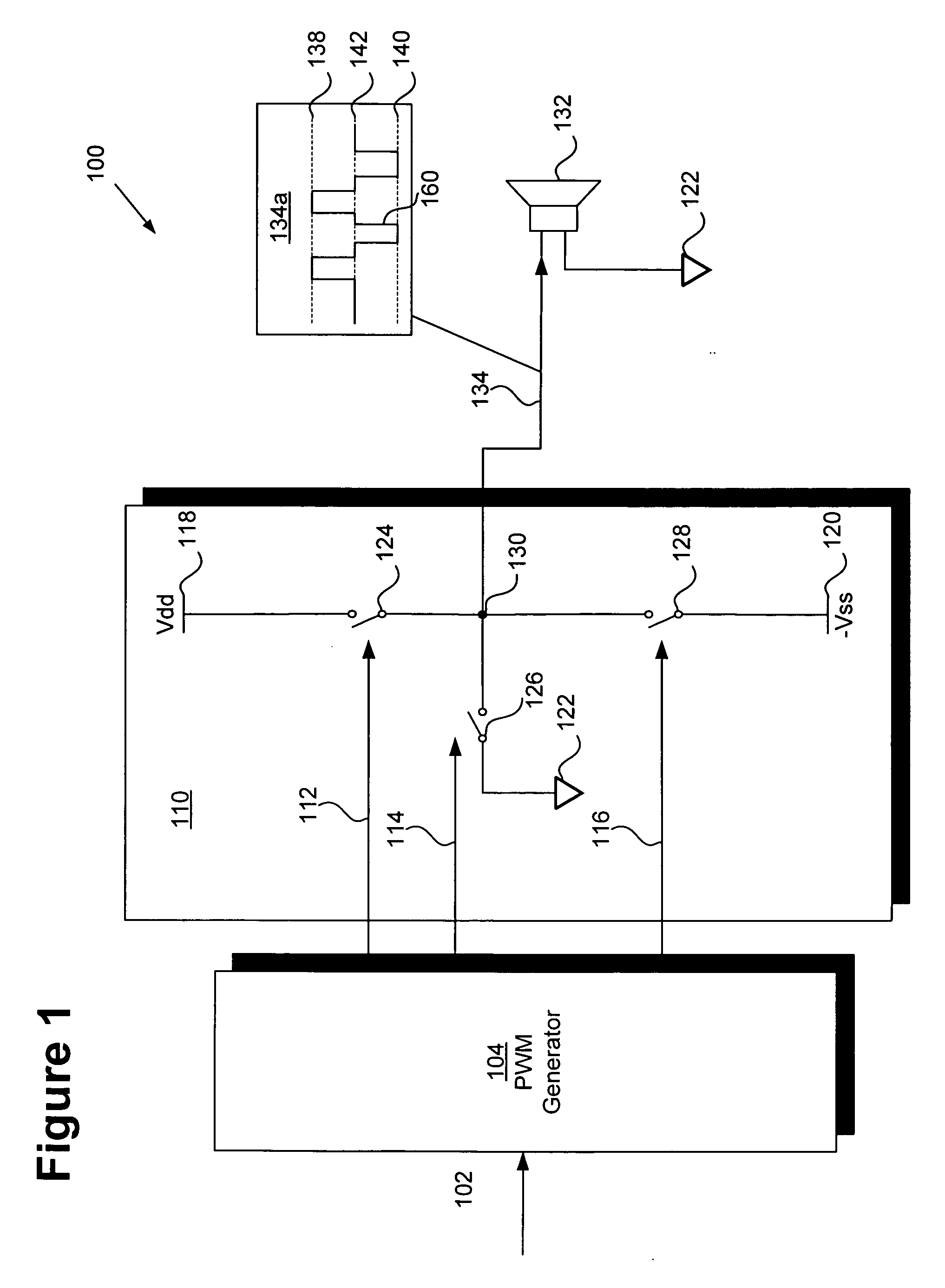
[0013]The present invention is directed to a ground-referenced common-mode amplifier circuit and related method. Although the invention is described with respect to specific embodiments, the principles of the invention, as defined by the claims appended herein, can obviously be applied beyond the specifically described embodiments of the invention described herein. Moreover, in the description of the present invention, certain details have been left out in order to not obscure the inventive aspects of the invention. The details left out are within the knowledge of a person of ordinary skill in the art.

[0014]The drawings in the present application and their accompanying detailed description are directed to merely exemplary embodiments of the invention. To maintain brevity, other embodiments of the invention, which use the principles of the present invention are not specifically described in the present application and are not specifically illustrated by the present drawings. It shoul...


PUM


Abstract

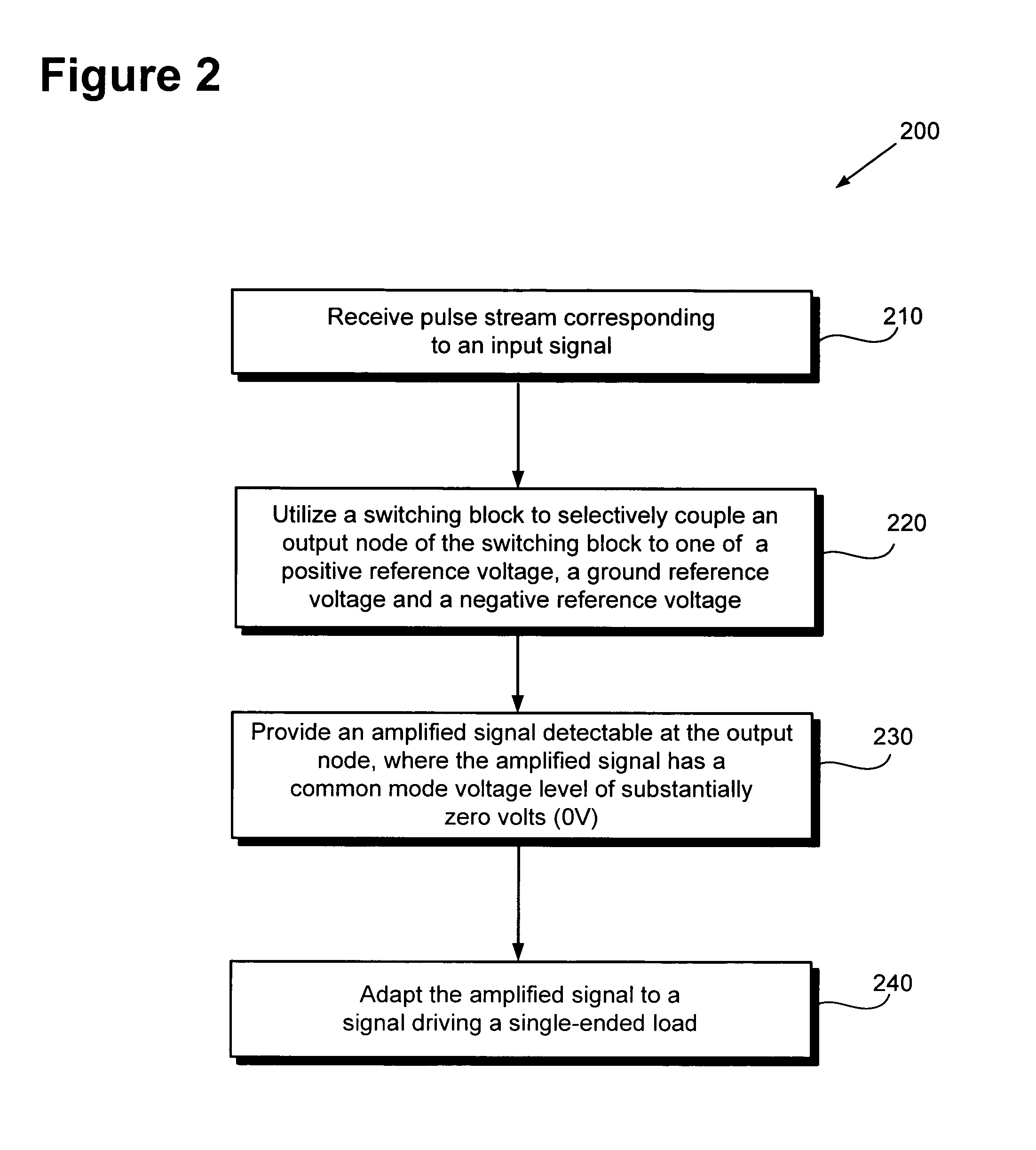
Disclosed is an amplifier circuit configured to amplify a pulse stream. The amplifier circuit comprises a switching block including a first switch operable to couple an output node of the switching block to a positive reference voltage, a second switch operable to couple the output node to a ground reference voltage and a third switch operable to couple the output node to a negative reference voltage. The amplifier circuit is configured to amplify the pulse stream into an amplified signal detectable at the output node such that the amplified signal has a common-mode voltage level substantially equal to zero volts. In one embodiment, the amplifier circuit is configured to amplify the pulse stream in accordance with a Class-D amplification scheme. In one embodiment, the output node can be directly connected to a load device without a DC blocking capacitor being interposed between the output node and the load device.

Description

BACKGROUND OF THE INVENTION[0001]1. Field of the Invention[0002]The present invention is generally in the field of electronic circuits and systems. More specifically, the present invention is in the field of power amplification circuitry.[0003]2. Background Art[0004]Power amplifiers play a critical role in driving an electrical load. Electronic systems frequently process a low voltage signal and amplify the signal to drive a higher powered load. For example, many music players process audio data at a low power level and amplify the audio data to a higher power level to drive a higher powered speaker or set of earphones. An efficient and cost effective power amplifier is therefore key to drive higher power loads.[0005]Unfortunately many power amplifier configurations are either inefficient or difficult to package. For example, a linear power amplifier typically utilizes a quiescent biasing current that consumes power even while the amplifier is idle, thereby degrading the power effic...

Claims


Application Information

Patent Timeline
IPC IPC(8): H03F3/217
CPCH03F3/217
Inventor JIANG, XICHENGSONG, JUNGWOO
Owner AVAGO TECH INT SALES PTE LTD
Learn More