Solid electrolytic capacitor and method of manufacturing the same
- Summary
- Abstract
- Description
- Claims
- Application Information
AI Technical Summary
Benefits of technology
Problems solved by technology
Method used
Image

Examples
first embodiment
[0026]In the following, a preferred example of a solid electrolytic capacitor of the present invention will be described. Here, a description will be given of a solid electrolytic capacitor including a capacitor element having an anode portion formed of a sintered body.
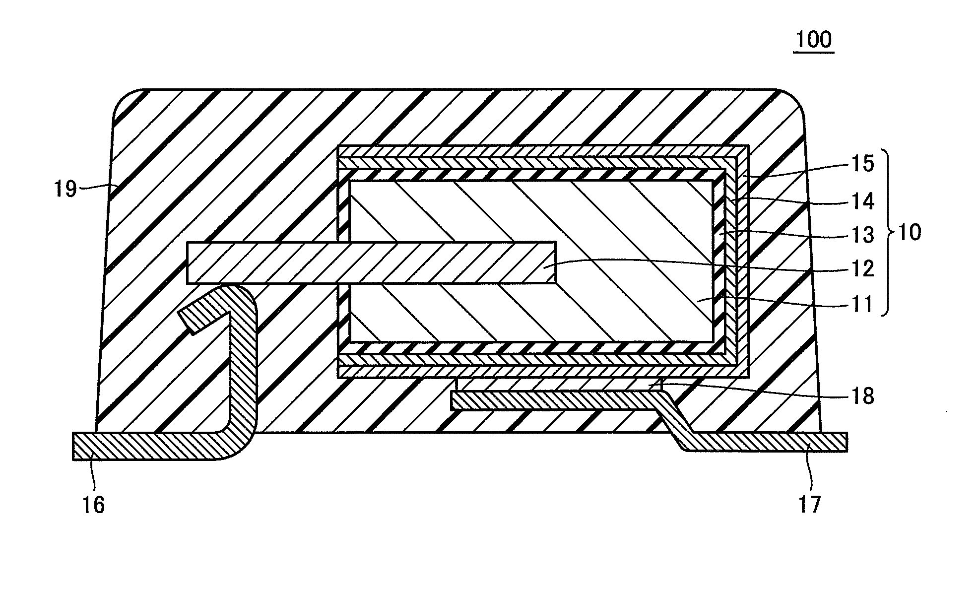
[0027]FIG. 1 is a cross section schematically showing an example of a structure of the solid electrolytic capacitor according to a first embodiment.
[0028]In FIG. 1, solid electrolytic capacitor 100 includes a capacitor element 10 having a dielectric coating 13, a solid electrolyte 14, and a cathode lead portion 15 that are formed in order on a surface of an anode portion 11 on which an anode lead portion 12 is erected. Anode lead portion 12 has an end exposed from anode portion 11 and electrically connected to an anode terminal 16, and cathode lead portion 15 is electrically connected to a cathode terminal 17 by a connecting portion 18. Capacitor element 10, one end of anode terminal 16 that is connected to anode lead...
second embodiment
[0040]In the following, another preferred example of a solid electrolytic capacitor of the present invention will be described using FIGS. 2 and 3. Here, a description will be given using a solid electrolytic capacitor including a capacitor element having an anode portion formed of a valve metal plate.
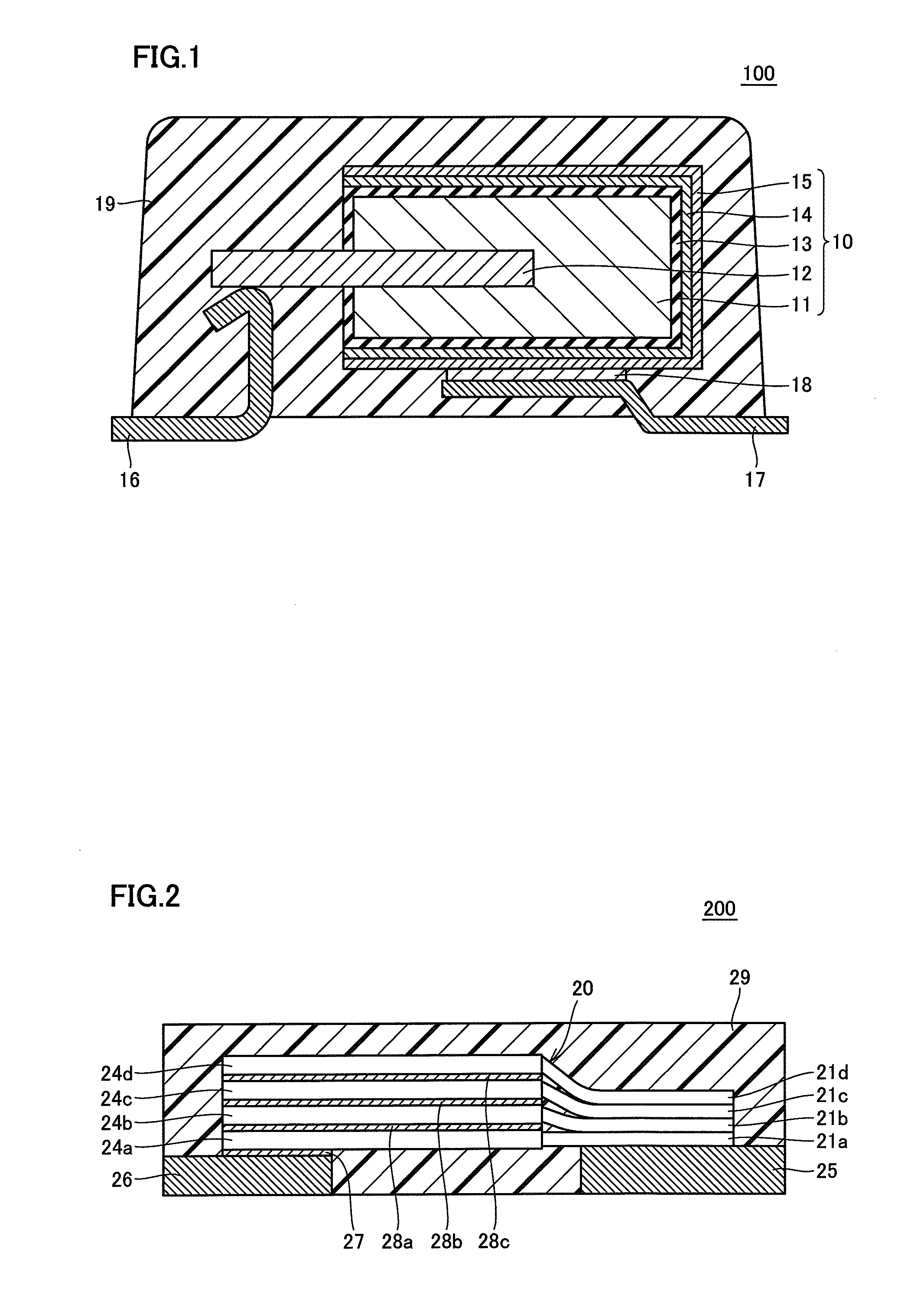
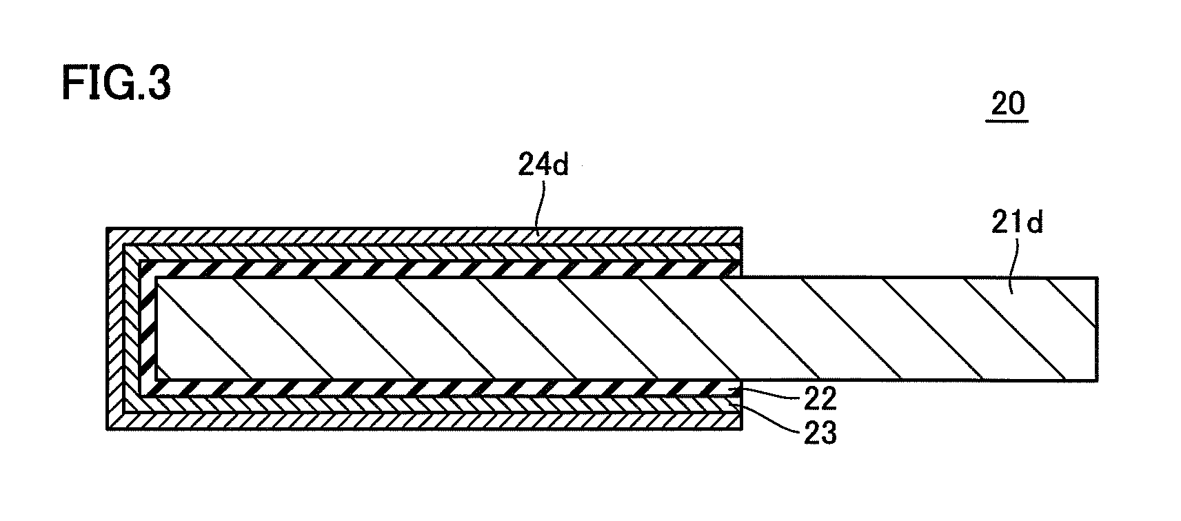
[0041]FIG. 2 is a cross section schematically showing an example of a structure of the solid electrolytic capacitor of a second embodiment, and FIG. 3 is a cross section schematically showing an example of the structure of the top capacitor element in FIG. 2.
[0042]In FIG. 2, solid electrolytic capacitor 200 includes four capacitor elements 20. Capacitor element 20 as shown in FIG. 3 has the structure in which a dielectric coating 22, a solid electrolyte 23, and a cathode lead portion 24d are formed in order on the surface of an anode lead portion 21d. While FIG. 3 is a cross section schematically showing the structure of top capacitor element 20 in FIG. 2, capacitor elements 20 are all...
third embodiment
[0058]In the following, a preferred example of the method of manufacturing a solid electrolytic capacitor of the present invention will be described. Here, a description will be given of a method of manufacturing a solid electrolytic capacitor including a capacitor element having an anode portion formed of a sintered body. FIGS. 4A to 4D are schematic cross sections illustrating an example of the method of manufacturing a solid electrolytic capacitor in a third embodiment, and the structure of the solid electrolytic capacitor to be manufactured is similar to that of solid electrolytic capacitor 100 in the first embodiment.
[0059]1. Preprocess
[0060]In this process, capacitor element 10 shown in FIG. 4A is produced. First, a known technique is followed to form anode portion 11 on which anode lead portion 12 is erected. Anode portion 11 shown in FIG. 4A can be formed for example in the following way. One end in the longitudinal direction of anode lead portion 12 is embedded in valve met...
PUM
| Property | Measurement | Unit |
|---|---|---|
| Temperature | aaaaa | aaaaa |
| Temperature | aaaaa | aaaaa |
| Thickness | aaaaa | aaaaa |
Abstract
Description
Claims
Application Information
 - R&D Engineer
- R&D Manager
- IP Professional
- Industry Leading Data Capabilities
- Powerful AI technology
- Patent DNA Extraction
Browse by: Latest US Patents, China's latest patents, Technical Efficacy Thesaurus, Application Domain, Technology Topic.
© 2024 PatSnap. All rights reserved.Legal|Privacy policy|Modern Slavery Act Transparency Statement|Sitemap