Electronic component and method of manufacturing the same

a technology of electronic components and manufacturing methods, applied in the direction of casings/cabinets/drawers, casings/cabinets/drawers details, variable capacitors, etc., can solve the problems of reducing the strength of electrode foils, preventing control of production processes, adversely affecting electrical characteristics, etc., to reduce the equivalent series resistance, small height, and small size

Inactive Publication Date: 2010-01-21
PANASONIC CORP
View PDF9 Cites 16 Cited by
  • Summary
  • Abstract
  • Description
  • Claims
  • Application Information

AI Technical Summary

Benefits of technology

[0008]This electronic component can have a small size and a small height while reducing its equivalent series resistance.

Problems solved by technology

The finer pits reduces the strength of the electrode foil, hence preventing control in production processes, such as lead wire connection and electrode foil rolling.
Thus, conventional solid electrolytic capacitor 601, upon having a smaller size and a smaller height, adversely affects electrical characteristics, such as a small capacitance and a large ESR.

Method used


Image

  • Electronic component and method of manufacturing the same
  • Electronic component and method of manufacturing the same
  • Electronic component and method of manufacturing the same

Examples


exemplary embodiment 1

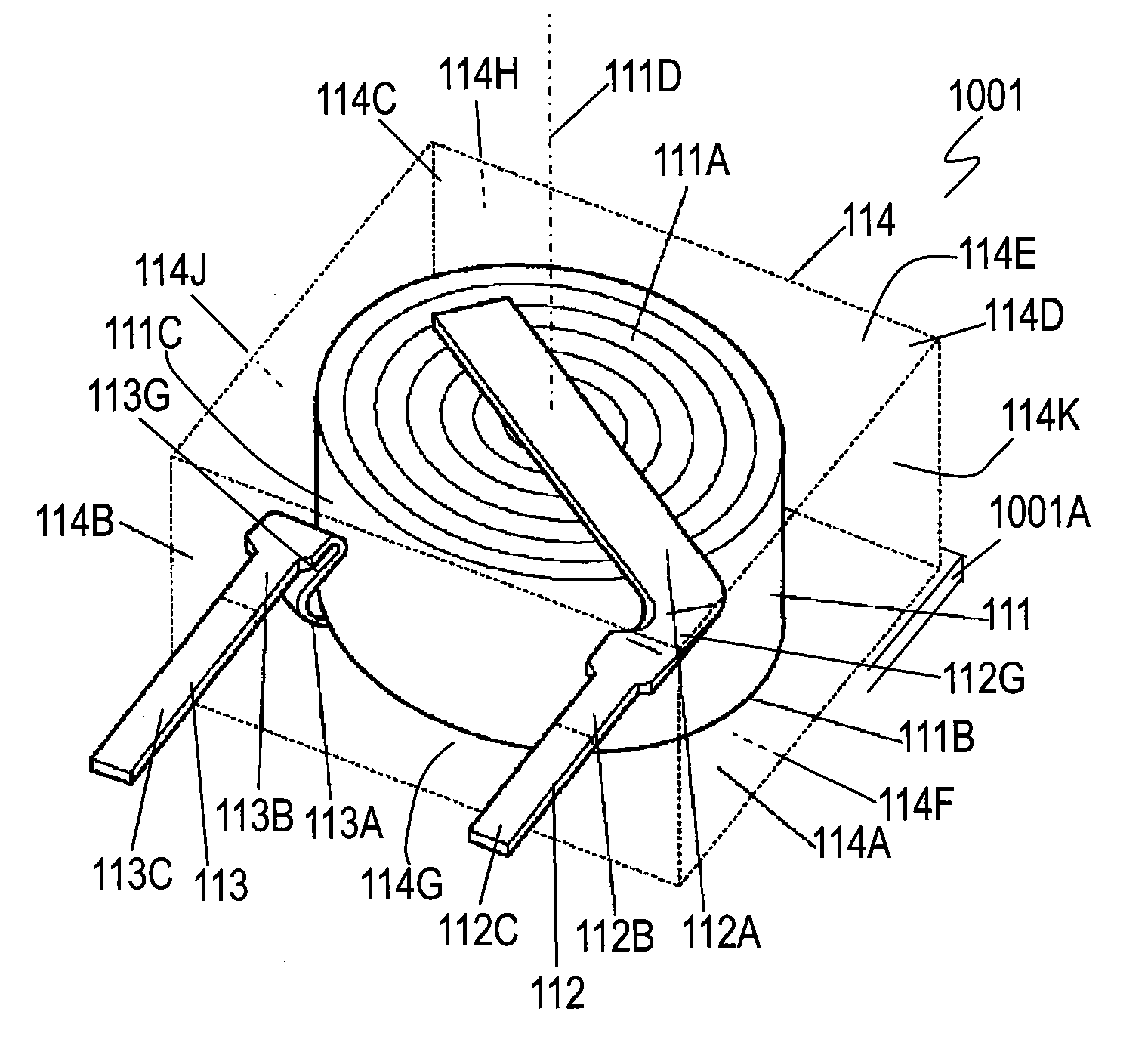
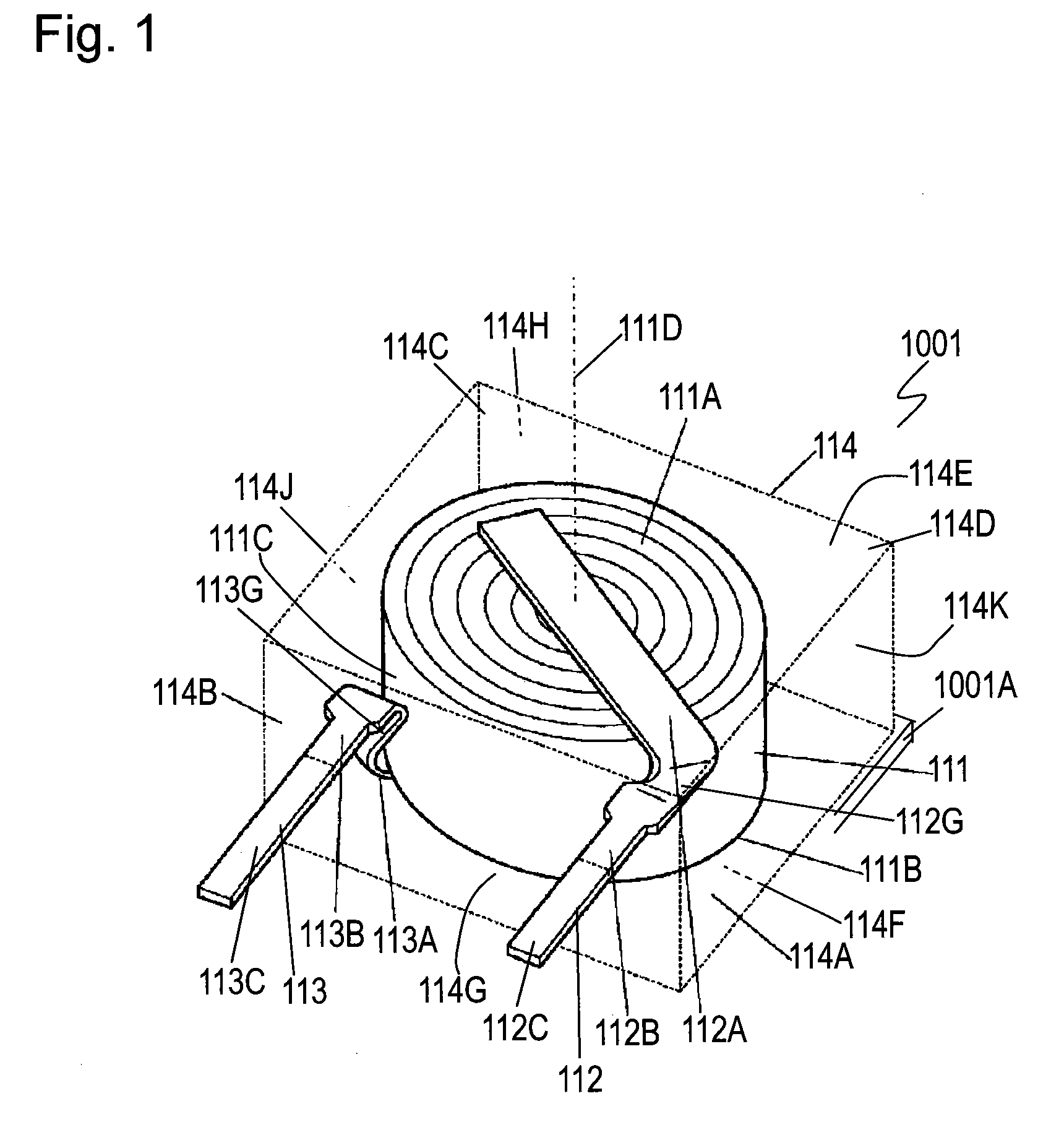
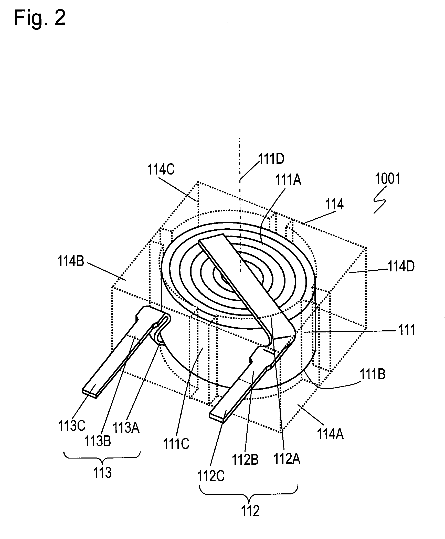
[0043]FIG. 1 is a perspective view of solid electrolytic capacitor 1001, an electronic component, according to Exemplary Embodiment 1 of the present invention. Solid electrolytic capacitor 1001 includes capacitor element 111, i.e. a functional element, having end surfaces 111A and 111B opposite to each other, positive electrode collector 112 joined to end surface 111A of capacitor element 111, negative electrode collector 113 joined to end surface 111B of capacitor element 111, and outer package114 for integrally covering capacitor element 111, positive electrode collector 112, and negative electrode collector 113. Capacitor element 111 is of a roll-type in which end surface 111A and end surface 111B function as a positive electrode and a negative electrode of capacitor element 111, respectively. Capacitor element 111 has a cylindrical shape extending along center axis 111D. Capacitor element 111 has circular end surfaces 111A and 111B opposite to each other arranged along center ax...

exemplary embodiment 2

[0093]FIG. 6 is a bottom perspective view of solid electrolytic capacitor 1003, an electronic component according to Exemplary Embodiment 2 of the present invention. In FIG. 6, components identical to those of solid electrolytic capacitor 1001 according to Embodiment 1 shown in FIGS. 1 to 3F are denoted by the same reference numerals, and their description will be omitted.

[0094]In solid electrolytic capacitor 1003 shown in FIG. 6, distal end portions 112C and 113C of terminals 112B and 113B exposed from outer package 114 are bent and extend along surfaces 114G and 114F of outer package 114. Solid electrolytic capacitor 1003 can be surface mounted on circuit board 1001A while surface 114F of outer package 114 contacts circuit board 1001A. Surface 114F of outer package 114 has grooves 118 and 128 formed therein. Distal end portions 112C and 113C of terminals 112B and 113B are fit into grooves 118 and 128.

[0095]FIG. 7 is a bottom perspective view of solid electrolytic capacitor 1004, a...

exemplary embodiment 3

[0104]FIG. 9 is a perspective view of solid electrolytic capacitor 2001, an electronic component according to exemplary Embodiment 3 of the present invention. Solid electrolytic capacitor 2001 includes capacitor element 211, a functional element, having end surfaces 211A and 211B opposite to each other, positive electrode collector 212 joined to end surface 211A of capacitor element 211, negative electrode collector 213 joined to end surface 211B of capacitor element 211, and outer package 214 for totally covering capacitor element 211, positive electrode collector 212, and negative electrode collector 213. Capacitor element 211 is a rolled-type. End surface 211A and end surface 211B function as a positive electrode and a negative electrode of capacitor element 211. Capacitor element 211 has a cylindrical shape extending along center axis 211D, and has circular end surfaces 211A and 211B opposite to each other along center axis 211D, and side surface 211C extending parallel to cente...


PUM

PropertyMeasurementUnit
widthsaaaaaaaaaa
shapeaaaaaaaaaa
conductiveaaaaaaaaaa

Abstract

An electronic component includes a functional element, first and second collectors joined to the functional element, and an outer package integrally covering the functional element and the first and second collectors. The functional element has first and second end surfaces having circular shapes and a side surface having a cylindrical shape extending along a center axis. The element includes first and second electrode foils rolled about the center axis and exposed from the first and second surfaces, respectively. The outer package has first and second surfaces parallel to the first and second end surfaces of the functional element, and has first to fourth corners as seen from a direction of the center axis. The first corner is adjacent to the second corner. The first and second terminals are arranged at the first and second corners of the outer package, respectively. This electronic component can have a small size and a small height while reducing its equivalent series resistance.

Description

FIELD OF THE INVENTION[0001]The present invention relates to an electronic component, such as a solid electrolytic capacitor, having a small equivalent series resistance, and a method of manufacturing the capacitor.BACKGROUND OF THE INVENTION[0002]Electronic components having a small equivalent series resistance (ESR) and being excellent in high frequency characteristics have recently required as digital equipments have been developed. Solid electrolytic capacitors employing solid electrolyte, such as manganese dioxide, polyaniline, polypyrrole, or polythiophene are put in the market as an electronic component. A capacitor including a roll type functional element having a rolled electrode foil and a capacitor including a stacked type functional element having electrode foils stacked in a thickness direction are known as the solid electrolytic capacitors. The roll type element can have a larger capacitance due to its structure and can be more efficiently produced than the stacked typ...

Claims


Application Information

Patent Timeline
Patent Type & Authority Applications(United States)
IPC IPC(8): H01G9/025H01G9/00
CPCH01G9/012H01G9/10Y10T29/435Y10T29/417H01G9/151
Inventor KAWAHARA, KAZUYAMURATA, YUUKIODA, TAKASHI
Owner PANASONIC CORP
Why Eureka
Try Eureka