Solid electrolytic capacitor and method for manufacturing the same

a solid electrolytic capacitor and electrolytic capacitor technology, applied in the direction of electrolytic capacitors, liquid electrolytic capacitors, coatings, etc., can solve the problems of hardly increasing the effective contact area between the cathode foil and the solid electrolyte, nickel foil is more expensive than aluminum foil, and the nickel plated layer cannot be formed uniformly inside, etc., to achieve low equivalent series resistance, high reliability, and large capacitance

Active Publication Date: 2010-08-12
PANASONIC CORP
View PDF6 Cites 15 Cited by
  • Summary
  • Abstract
  • Description
  • Claims
  • Application Information

AI Technical Summary

Benefits of technology

[0019]This solid electrolytic capacitor has a large capacitance and a low equivalent series resistance while being inexpensive and highly reliable.

Problems solved by technology

The non-valve metal foil disclosed in Patent Document 1 cannot be roughened by an etching process, and hence, can hardly increase an effective contact area between the cathode foil and the solid electrolyte.
Further, the nickel foil is more expensive than aluminum foil.
However, the nickel plated layer can hardly be formed uniformly inside pores formed in the roughed surface of the aluminum foil.
Further, the aluminum foil can hardly be bonded to the nickel plated layer securely.
However, technical matters of the etching process and the mechanical strength of the aluminum foil restrict the increase of the surface area of the anode body, hence preventing capacitor 501 from having a large greater capacitance.
As the number of capacitor elements 211 increases, the amounts of expensive materials, such as the silver paste and the conductive adhesive, accordingly making capacitor 501 expensive.

Method used


Image

  • Solid electrolytic capacitor and method for manufacturing the same
  • Solid electrolytic capacitor and method for manufacturing the same
  • Solid electrolytic capacitor and method for manufacturing the same

Examples


exemplary embodiment 1

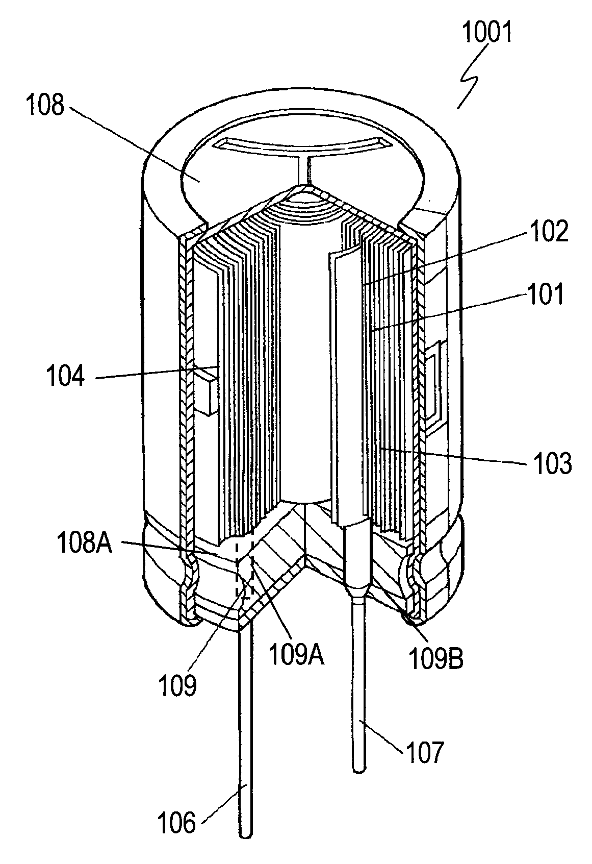
[0077]FIG. 1 is a perspective view of solid electrolytic capacitor 1001 in accordance with Exemplary Embodiment 1 of the present invention. Capacitor 1001 includes capacitor element 104, case 108 for accommodating capacitor element 104 therein, anode terminal 106 coupled to capacitor element 104, cathode terminal 107 coupled to capacitor element 104, and sealing member 109 for sealing opening 108A of case 108. Sealing member 109 is made of resin-vulcanized butyl rubber, and has hole 109A and hole 109B through which anode terminal 106 and cathode terminal 107 extend, respectively. Capacitor element 104 includes anode foil 101, cathode foil 102, and separator 103 which are stacked and wound together. Anode terminal 106 and cathode terminal 107 are coupled to anode foil 101 and cathode foil 102, respectively.

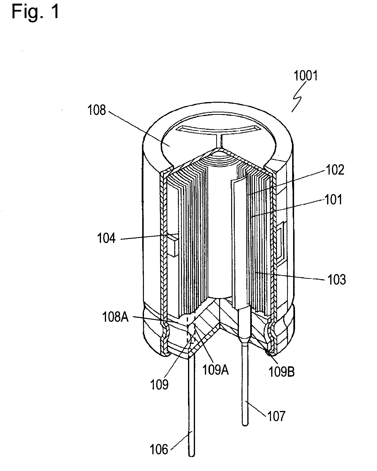
[0078]FIG. 2 is a schematic cross-sectional view of capacitor element 104. Anode foil 101 includes anode base 101A made of highly-pure aluminum, rough surface layer 101B provided o...

exemplary embodiment 2

[0115]A solid electrolytic capacitor in accordance with Exemplary Embodiment 2 includes nickel layer 102B made of nickel and nickel oxide provided only on surface 1102A of cathode base 102A of cathode foil 102 shown in FIG. 2. Any nickel layer is not formed on another surface 2102A of cathode base 102A. Surface 2102A contacts solid electrolyte 105. FIG. 9 shows measurement results of a capacitance and an equivalent series resistance (ESR) of the solid electrolytic capacitor in accordance with Embodiment 2 similarly to the capacitor according to Embodiment 1,

[0116]As shown in FIG. 9, the capacitor according to Embodiment 2 has a capacitance about 3.8 times the capacitance of Comparative Example 1, and has an ESR about ¾ the ESR of Comparative Example 1. The capacitor in accordance with Embodiment 2 thus has excellent performance. Nickel layer 102B formed only on surface 1102A of cathode base 102A foes not produce a capacitance at surface 2102A.

[0117]However, nickel layer 102B is form...

exemplary embodiment 3

[0118]FIG. 11 is a schematic cross-sectional view of capacitor element 104A included in a solid electrolytic capacitor in accordance with Exemplary Embodiment 3 of the present invention. In FIG. 11, components identical to those of capacitor 104 shown in Fig. are denoted by the same reference numerals, and their description is omitted. Capacitor element 104A includes cathode foil 110 instead of cathode foil 102 of capacitor element 104 shown in FIG. 2. Cathode foil 110 includes cathode base 110A made of aluminum foil and nickel layer 110B formed on surface 1110A of cathode base 110A and made of nickel and nickel oxide. Surface 1110A of cathode base 110A is roughened by an etching process, and has a large number of pores 3110A formed thereon. Nickel layer 110B is provided to portion 4110A of surface 1110A where no pore is formed, so that no nickel layer is provided inside pores 3110A. Solid electrolyte 105 contacts pores 3110A of cathode base 110A.

[0119]In capacitor element 104A in a...


PUM

PropertyMeasurementUnit
diametersaaaaaaaaaa
thicknessesaaaaaaaaaa

Abstract

A solid electrolytic capacitor includes an anode foil, a solid electrolyte provided on the anode foil and made of conductive polymer, and a cathode foil provided on the solid electrolyte and facing the anode foil across the solid electrolyte. The anode foil includes an anode base made of aluminum, a rough surface layer made of aluminum and provided on a surface of the anode base, and a dielectric oxide layer provided on the rough surface layer and contacting the solid electrolyte. The cathode foil includes a cathode base made of aluminum, and a nickel layer provided on a surface of the cathode base and contacting the solid electrolyte. The nickel layer faces the dielectric oxide layer of the anode foil across the solid electrolyte. The nickel layer is made of nickel and nickel oxide. This solid electrolytic capacitor has a large capacitance and a low equivalent series resistance while being inexpensive and highly reliable.

Description

TECHNICAL FIELD[0001]The present invention relates to a solid electrolytic capacitor including solid electrolyte made of conductive polymer, and to a method for manufacturing the capacitor.BACKGROUND ART[0002]As electronic apparatuses operate at higher frequencies, capacitors used in the apparatuses are demanded to have a lower equivalent series resistance (ESR), excellent impedance characteristics at the high frequencies, and large capacitance. To meet these demands, solid electrolytic capacitors employing solid electrolyte made of conductive polymer having higher electric conductivity have been developed.[0003]A roll-type solid electrolytic capacitor has been in market to meet the demand of a large capacitance. This capacitor includes an anode foil, a cathode foil, and a separator which are wound together. This solid electrolytic capacitor is more excellent not only in its life time and temperature characteristics but also in high-frequency characteristics than other capacitors, a...

Claims


Application Information

Patent Timeline
Patent Type & Authority Applications(United States)
IPC IPC(8): H01G9/045B05D5/12H01G9/048
CPCH01G9/0425Y10T29/417H01G9/151H01G9/055
Inventor AOYAMA, TATSUJIYOSHINO, TSUYOSHI
Owner PANASONIC CORP
Why Eureka
Try Eureka