

Sterlizing system, and loading/unloading device therefor
- Summary
- Abstract
- Description
- Claims
- Application Information
AI Technical Summary
Benefits of technology
Problems solved by technology
Method used
Image

Examples
Embodiment Construction
[0023]Several embodiments of the present invention will be described in more detail below with reference to the accompanying drawings in order for those skilled in the art to be able to carry out the invention. The invention may, however, be embodied in many different forms and should not be construed as limited to the embodiments set forth herein. Rather, these embodiments are provided so that this disclosure will be thorough and complete, and will fully convey the scope of the invention to those skilled in the art. The embodiments do not limit the invention, but the invention is only limited by the appended patent claims. Furthermore, the terminology used in the detailed description of the particular embodiments illustrated in the accompanying drawings is not intended to be limiting of the invention.
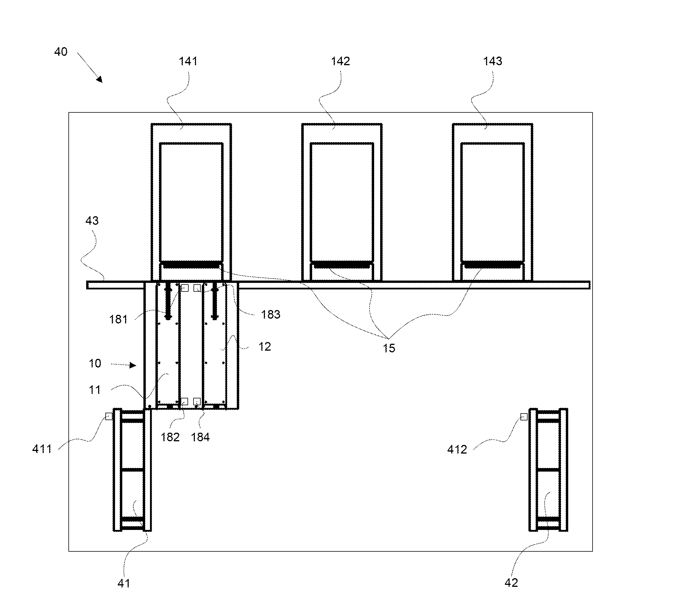
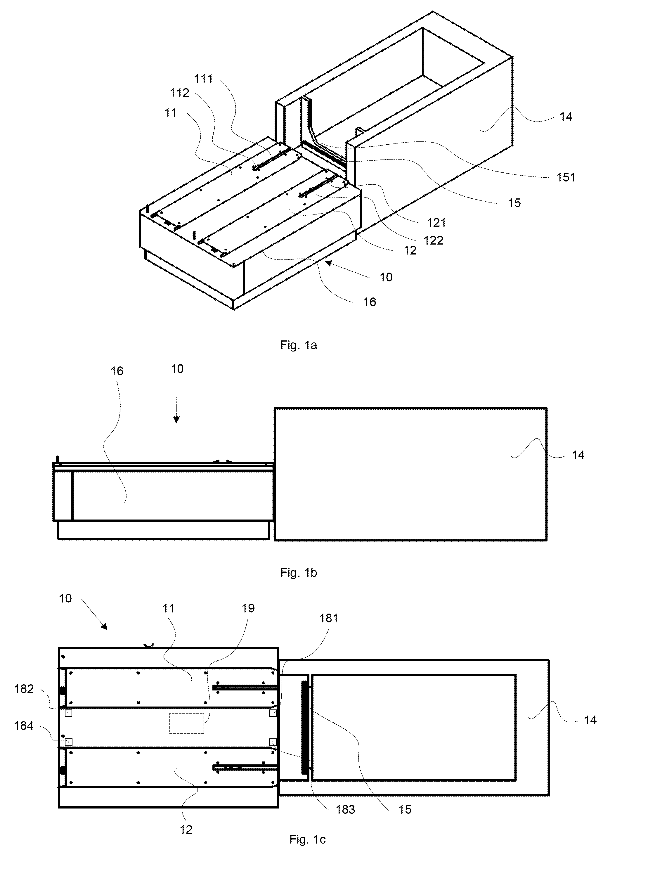
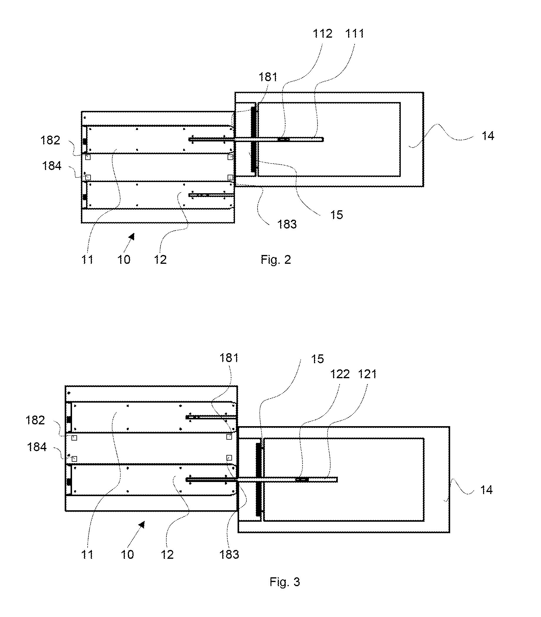
[0024]The following description focuses on embodiments applicable to a sterilizing system and in particular to a loading / unloading device for a front loaded sterilizing device.
[0025]An...
PUM
 Abstract
Description
Claims
Application Information