Cable-end connector

a cable-end connector and connector technology, applied in the direction of coupling devices, two-part coupling devices, electrical apparatus, etc., can solve the problems of lowering the signal transmission performance, high stability and rapid speed of signal transmission, and achieve the effect of effectively eliminating electromagnetic interference, preventing sticking after connection, and effectively sealing off outside moistur

Inactive Publication Date: 2011-10-27
LU YUEH CHIUNG
View PDF6 Cites 8 Cited by
  • Summary
  • Abstract
  • Description
  • Claims
  • Application Information

AI Technical Summary

Benefits of technology

[0010]The present invention has been accomplished under the circumstances in view. It is the main object of the present invention to provide a cable-end connector, which effectively eliminates electromagnetic interference, effectively seals off outside moisture, and prevents sticking after connection with a mating connector.
[0011]To achieve this and other objects of the present invention, a cable-end connector is affixed to one end of a coaxial cable for connection to a mating connector, comprising a metal locknut, an elastically deformable cylindrical casing, a metal core tube and a barrel. The locknut comprises a retaining structure located on a front end thereof that comprises a retaining groove of substantially inverted -shaped cross section and a stop edge disposed at one side of the retaining groove. The cylindrical casing comprises a retaining structure located on a rear end thereof that comprises a retaining flange extending around the periphery for engaging the retaining groove of the retaining structure of the locknut. The metal core tube comprises a rear stop flange that has a front stop edge stopped against the stop edge of the retaining structure of the locknut to enhance the electromagnetic wave shielding effect. After the cable-end connector is assembled with a mating connector, the front stop edge of the rear stop flange is stopped against the stop edge of the retaining structure of the locknut, and the retaining flange of the retaining structure of cylindrical casing is stopped against the periphery of the retaining groove of the retaining structure of the locknut and elastically deformed so that the retaining flange and the rear stop flange block the clearance between the retaining structure of the locknut and the retaining structure of the cylindrical casing, prohibiting outside moisture from passing through the clearance into the inside of the locknut or the inside of the cylindrical casing.
[0012]Further, the diameter of the rear stop flange is greater than the inner diameter of the retaining groove of the retaining structure of the locknut, and the contact area between the rear stop flange and the stop edge of the retaining structure of the locknut is large enough to enhance the electromagnetic wave shielding effect. Because there is a large contact area between the front stop edge of the rear stop flange of the core tube and the stop edge of the retaining structure of the locknut, the rear stop flange of the core tube can be shortened, saving much the consumption of the metal material and reducing the manufacturing cost.
[0013]Further, the retaining flange of the retaining structure of flexible cylindrical casing is stopped against the periphery of the retaining groove of the retaining structure of the locknut and the extension portion that suspends in the locknut is stopped by the rear stop flange of the core tube, and therefore the retaining flange is forced to deform elastically and to block the clearance between the retaining structure of the locknut and the retaining structure of the cylindrical casing, prohibiting outside moisture from passing through the clearance into the inside of the cylindrical casing to moisten the braided metal wrapper (woven copper shield) of the coaxial cable or to destruct the shielding effect.

Problems solved by technology

Following fast development of communication technology, signal transmission requires high stability and rapid speed.
Further, due to a small contact area between the end flange C1 of the he core tube C and the stop edge A12 of the locknut A, outside moisture may pass to the inside of the cable-end connector to moisten the internal components, lowering the signal transmission performance.

Method used


Image

  • Cable-end connector
  • Cable-end connector
  • Cable-end connector

Examples


Embodiment Construction

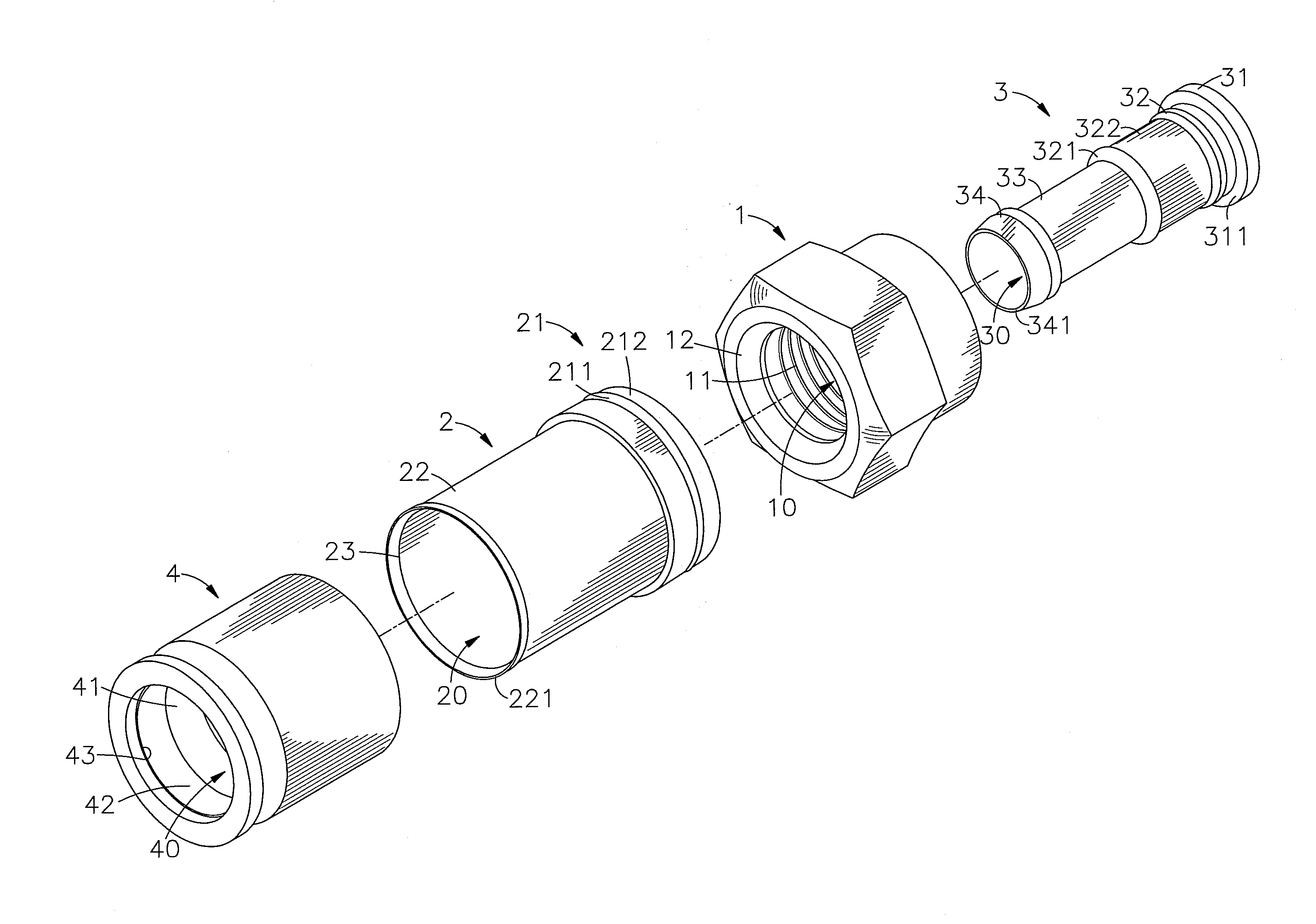
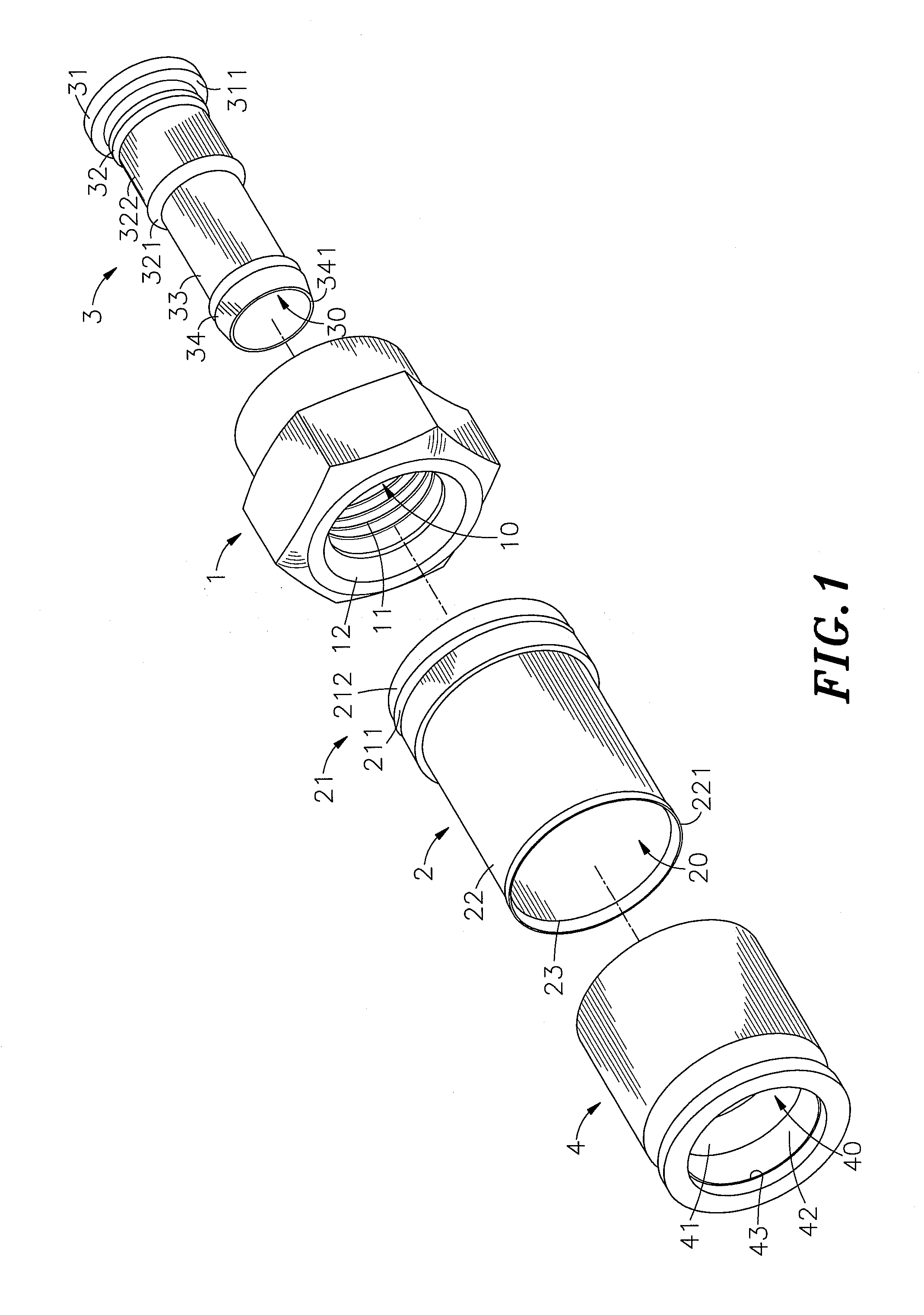
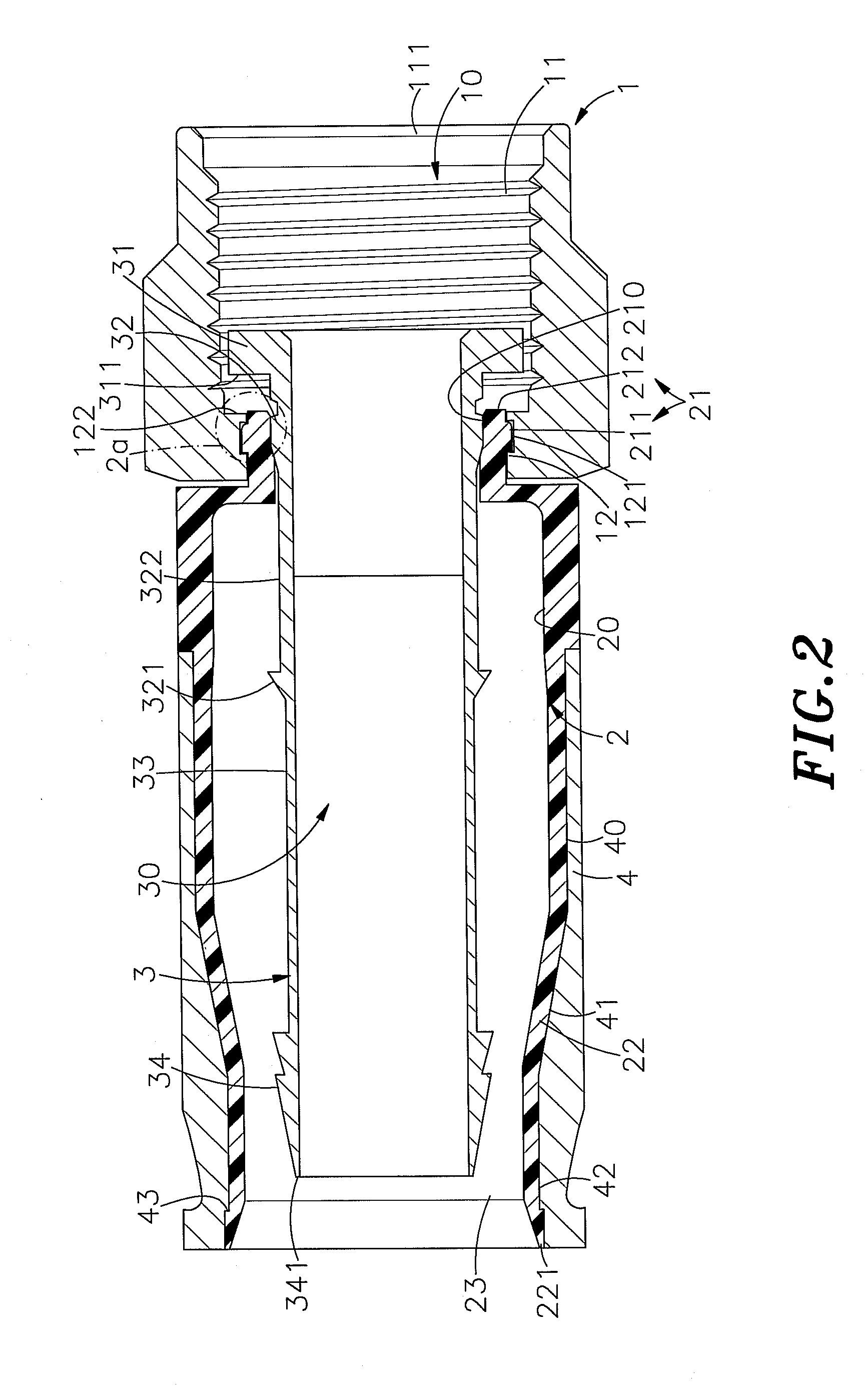
[0022]Referring to FIGS. 1˜3, a cable-end connector in accordance with the present invention is shown comprising a locknut 1, a cylindrical casing 2, a core tube 3 and a barrel 4.

[0023]The locknut 1 can be a polygonal nut or peripherally embossed circular nut made of metal, having an axially extending center through hole 10, a rear orifice 111 at one end, namely, the rear end of the center through hole 10, a retaining structure 12 at an opposite end, namely, the front end of the center through hole 10, and an inner thread 11 formed in the center through hole 10 between the rear orifice 111 and the retaining structure 12. The retaining structure 12 comprises a retaining groove 121 of substantially inverted -shaped cross section extending around the inside wall of the locknut 1 and a stop edge 122 disposed at one side of the retaining groove 121 adjacent to the inner thread 11.

[0024]The cylindrical casing 2 is made of an elastic material, having an axial hole 20 extending through oppo...


PUM


Abstract

A cable-end connector includes a metal locknut having an axially extending center through hole, a rear orifice and a retaining structure, the retaining structure of the locknut defining a retaining groove and a stop edge, an elastically deformable cylindrical casing having an axial hole and a retaining structure for engagement with the retaining structure of the locknut and defining with the retaining structure of the locknut a clearance, the retaining structure of the cylindrical casing having a retaining flange for engaging the retaining groove of the retaining structure of the locknut, and a metal core tube mounted in the locknut and the cylindrical casing and having a rear stop flange for stopping against the stop edge of the locknut to block the clearance and to force the retaining flange of the retaining structure of the cylindrical casing into engagement with the retaining groove of the retaining structure of the locknut tightly, thereby sealing off outside moisture and enhancing the electromagnetic wave shielding effect.

Description

[0001]This application claims the priority benefit of Taiwan patent application number 099207616, filed on Apr. 26, 2010.BACKGROUND OF THE INVENTION[0002]1. Field of the Invention[0003]The present invention relates electrical connectors and more particularly to a cable-end connector consisting of a metal locknut, an elastically deformable cylindrical casing, a metal core tube and a barrel for connecting a coaxial cable to a mating connector that effectively seals off outside moisture and greatly enhances the electromagnetic wave shielding effect.[0004]2. Description of the Related Art[0005]Following fast development of communication technology, signal transmission requires high stability and rapid speed. In consequence, different communication wire materials, from the early flat cable design to the modern round cable and optical cable designs, have been created to enhance signal transmission speed and capacity. Subject to the application of telephone technology, video technology and...

Claims


Application Information

Patent Timeline
Patent Type & Authority Applications(United States)
IPC IPC(8): H01R9/05
CPCH01R9/0524H01R13/6592H01R13/6583H01R24/40
Inventor LU, YUEH-CHIUNG
Owner LU YUEH CHIUNG
Why Eureka
Try Eureka