Spinal cord stimulator lead anchor

a technology of stimulator and lead anchor, which is applied in the direction of spinal electrodes, internal electrodes, therapy, etc., can solve the problems of high cost of this technology, adverse consequences, and migration, and achieve the effect of significantly minimizing migration

Inactive Publication Date: 2011-10-27
HAMILTON DENNISON R
View PDF0 Cites 11 Cited by
  • Summary
  • Abstract
  • Description
  • Claims
  • Application Information

AI Technical Summary

Benefits of technology

In an embodiment of the present invention, an anchor staple receives and holds an implanted lead at a selected location along the spine. The staple presents a loop to accommodate the lead or suture sleeve, and is closed to engage bone, ligament, fascia or skin to apply a constant pressure to secure the lead and thereby prevent, or significantly minimize migration. The

Problems solved by technology

In addition to the high cost of this technology, there are risks of adverse consequences.
A significant adverse event is lead migration which may occur approximately twenty percent of the time.
Correction of the migration may be expensive

Method used


Image

  • Spinal cord stimulator lead anchor
  • Spinal cord stimulator lead anchor
  • Spinal cord stimulator lead anchor

Examples


Embodiment Construction

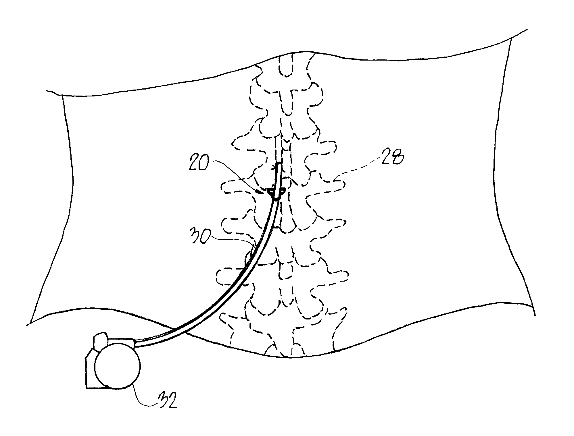
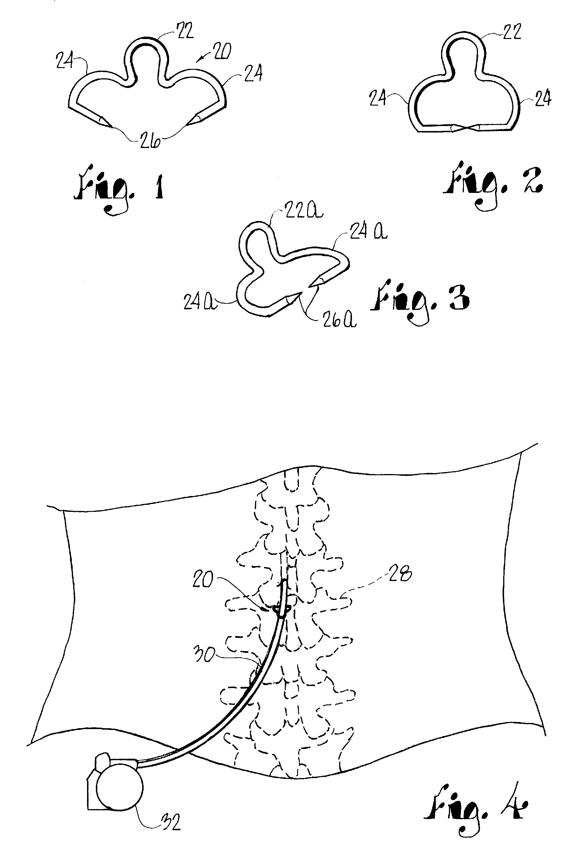
Referring initially to FIGS. 1 and 2, an anchor staple 20 of the present invention is shown open prior to application in FIG. 1 and in a closed condition in FIG. 2 and preferably comprises a titanium rod having a central loop 22 and a pair of spaced, opposed legs 24 of a generally C-shaped configuration presenting spaced, pointed distal ends 26 initially presenting an opening therebetween. In use, as will be discussed hereinbelow, the legs 24 are closed as shown in FIG. 2 to engage and embrace an anchor point adjacent the spine presented by bone, ligament, fascia or skin at the location under treatment. This is illustrated in FIG. 4 where the spinal column 28 of a patient is shown in broken lines. A lead 30 extending from an implanted pulse generator illustrated at 32 is secured by the staple 20. Depending upon the particular installation, as shown in FIG. 3 the plane of the loop 22a may be disposed at an acute angle to the plane presented by the opposed legs 24a, 26a at an angle, f...


PUM


Abstract

The lead of a spinal cord stimulator implanted along the spinal cord of a recipient is secured by an anchor staple at a selected location. The anchor staple comprises a loop that receives and holds the lead at the selected location along the spine. A pair of spaced legs extend from the loop and present an initially open configuration for receiving an anchor point presented by bone, ligament, fascia or skin. The legs are closed to engage the anchor point and thereby positively secure the lead to prevent migration of the implanted lead. Several staples may be applied in a row to assure optimal positioning of the lead.

Description

This invention relates to the treatment of back pain by an implanted spinal cord stimulator and, in particular, to the prevention of the adverse affect of a lead migration which negates the effectiveness of the treatment.BACKGROUND OF THE INVENTIONIt has been estimated that eighty percent of the population of the United States will suffer from back pain at some time in their life. A portion of the affected population will suffer from intractable back pain that is unresponsive to surgical intervention, injection therapy, physical therapy or narcotic analgesics. Those unresponsive to conventional treatment are candidates for a spinal cord stimulator which is implanted in a manner similar to a heart pacemaker. Leads with electrodes are placed along the spinal cord in the epidural space and are energized by an implantable pulse generator which sends an electrical impulse through the leads and electrodes over the spinal cord to produce a sense of numbness or tingling where the person is ...

Claims


Application Information

Patent Timeline
IPC IPC(8): A61N1/05
CPCA61N1/0558
Inventor HAMILTON, DENNISON R.
Owner HAMILTON DENNISON R
Why Eureka
Try Eureka