Circuit and method for driving a light emitting diode for a backlight, and backlight driving apparatus using the same

a technology of light-emitting diodes and backlights, which is applied in the direction of electric digital data processing, instruments, computing, etc., can solve the problems of low color reproduction and white light generation, slow response speed, and environmental harm, and achieve the effect of reducing the number of backlights

Inactive Publication Date: 2011-11-03
MAGNACHIP SEMICONDUCTOR LTD
View PDF11 Cites 15 Cited by
  • Summary
  • Abstract
  • Description
  • Claims
  • Application Information

AI Technical Summary

Benefits of technology

[0029]In another general aspect, there is provided a method for driving a light emitting diode (LED) for a backlight, including filtering a pulse width modulation (PWM) signal, stabilizing a du

Problems solved by technology

Since a backlight using the CCFL uses mercury, it is harmful to environment and has a slow response speed.
Furthermore, it has disadvantages of low color reproduction and generation of preset white light.
When the controller or the MCU generates the PWM signal for adjusting the brightness of the LED and provides the LED driving circuit with the PWM signal, the PWM signal is affected by unde

Method used


Image

  • Circuit and method for driving a light emitting diode for a backlight, and backlight driving apparatus using the same
  • Circuit and method for driving a light emitting diode for a backlight, and backlight driving apparatus using the same
  • Circuit and method for driving a light emitting diode for a backlight, and backlight driving apparatus using the same

Examples


Embodiment Construction

[0040]The following detailed description is provided to assist the reader in gaining a comprehensive understanding of the methods, apparatuses, and / or systems described herein. Accordingly, various changes, modifications, and equivalents of the systems, apparatuses and / or methods described herein will be suggested to those of ordinary skill in the art. The progression of processing steps and / or operations described is an example; however, the sequence of steps and / or operations is not limited to that set forth herein and may be changed as is known in the art, with the exception of steps and / or operations necessarily occurring in a certain order. Also, descriptions of well-known functions and constructions may be omitted for increased clarity and conciseness.

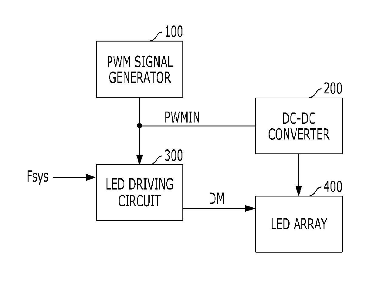
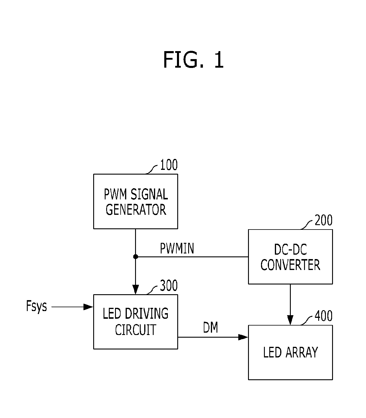
[0041]FIG. 1 is an example of a block diagram illustrating the configuration of a backlight driving apparatus. Referring to FIG. 1, the backlight driving apparatus includes a pulse width modulation (PWM) signal generator 100, a d...


PUM


Abstract

A circuit and method for driving a light emitting diode for a backlight, and a backlight driving apparatus using the same is provided. A circuit for driving a light emitting diode (LED) for a backlight includes a filtering unit configured to receive a pulse width modulation (PWM) signal and remove noise of a predetermined band, a duty stabilization unit configured to stabilize a duty of a PWM signal filtered by the filtering unit, a dimming signal generation unit configured to generate a dimming signal based on a PWM signal stabilized by the duty stabilization unit, and an LED driving unit configured to drive the LED for the backlight based on the dimming signal generated by the dimming signal generation unit.

Description

CROSS-REFERENCE TO RELATED APPLICATIONS[0001]This application claims the benefit under 35 U.S.C. §119(a) of Korean Patent Application No. 10-2010-0040882, filed on Apr. 30, 2010, the entire disclosure of which is incorporated herein by reference for all purposes.BACKGROUND[0002]1. Field[0003]The following description relates to a circuit for driving a light emitting diode (LED) for a backlight, and more particularly, to a circuit and a method for driving an LED for a backlight, which can stably maintain the brightness of the LED by substantially preventing the occurrence of a flicker, and a backlight driving apparatus using the same.[0004]2. Description of the Related Art[0005]A liquid crystal display (LCD), which is a representative flat panel display, displays images by using the electrical and optical properties of liquid crystal. The LCD has been extensively used due to the advantages of slimness, lightweight, low power consumption, and a low driving voltage, as compared with ot...

Claims


Application Information

Patent Timeline
IPC IPC(8): G09G5/10G09G3/30
CPCG09G3/3406G09G2360/145G09G2320/064G09G2320/0247H05B45/37
Inventor BAIK, SEUNG-BEOMKIM, MI-JINKIM, EUNG-SUENSHIN, DU-SU
Owner MAGNACHIP SEMICONDUCTOR LTD
Why Eureka
Try Eureka