Grid plate for lead acid storage battery, plate, and lead acid storage battery provided with same plate

Active Publication Date: 2011-11-10
SHIN KOBE ELECTRIC MASCH
View PDF1 Cites 3 Cited by
  • Summary
  • Abstract
  • Description
  • Claims
  • Application Information

AI Technical Summary

Benefits of technology

[0021]In accordance with the present invention, charging and discharging of the lead acid storage battery during operation are performed while the SOC is kept in a range of 30 to 90%, and the voltage of the lead acid storage battery is held in a range of 1.80 to 2.42 V per cell, making it possible to operate the lead acid storage battery in an insufficiently charged state, and greatly extend its service life.
[0022]In the present invention, a reference temperature is set to 25° C., and charging and discharging of the lead acid storage battery is carried out while the battery voltage is kept in a specified range (1.80 to 2.42 V/cell) when the ambient temperature of the lead acid storage battery is at the reference temperature. When the ambient temperature has increased or decreased relative to the reference temperature (25° C.), the upper limit value and the lower limit value of the specified range is increased or reduced by a correction amount selected in the range of 4 mV/° C. to 6 mV/° C. per cell in accordance with the increase or decrease in the ambient temperature from the reference temperature to obtain a corrected voltage range. It is possible to prevent the lead acid storage battery from becoming overcharged when the ambient temperature is high, to suppress accelerated corrosion of the positive grid and loss of electrolyte, and to extend service life in the case that the lead acid storage battery is charged and discharged in a state in which the battery voltage is kept in the corrected voltage range. In other words, charging efficiency is good even when the voltage is low at high temperatures. Therefore, the lead acid storage battery can be prevented from entering an overcharged state by carrying out operation so that the range of the battery voltage is shifted to a lower range. Conversely, since the charging efficiency is very poor at low temperatures, the occurrence of sulfation due to insufficient charging can be minimized by correcting the battery voltage during operation to account for tempe

Problems solved by technology

It is well known that the amount of power generated by a natural energy power generation device fluctuates in an irregular manner and such fluctuation is therefore a considerable drawback to the power quality of the transmission grid when the natural energy power generation device is directly linked to the transmission grid.
In the case that the natural energy power generation device is linked to the transmission grid, a power company may not be able to satisfy the required linkage conditions when there is considerable fluctuation in the power supplied from a power generation device.
However, since the amount of power generated by a natural energy power generation device fluctuates in an irregular manner, there is a problem in that a lead acid storage battery may continue a state of over-discharge (e.g., a state in which the SOC is 30% or less) or a state of overcharge (a state in which the SOC excee

Method used


Image

  • Grid plate for lead acid storage battery, plate, and lead acid storage battery provided with same plate
  • Grid plate for lead acid storage battery, plate, and lead acid storage battery provided with same plate
  • Grid plate for lead acid storage battery, plate, and lead acid storage battery provided with same plate

Examples


example 1

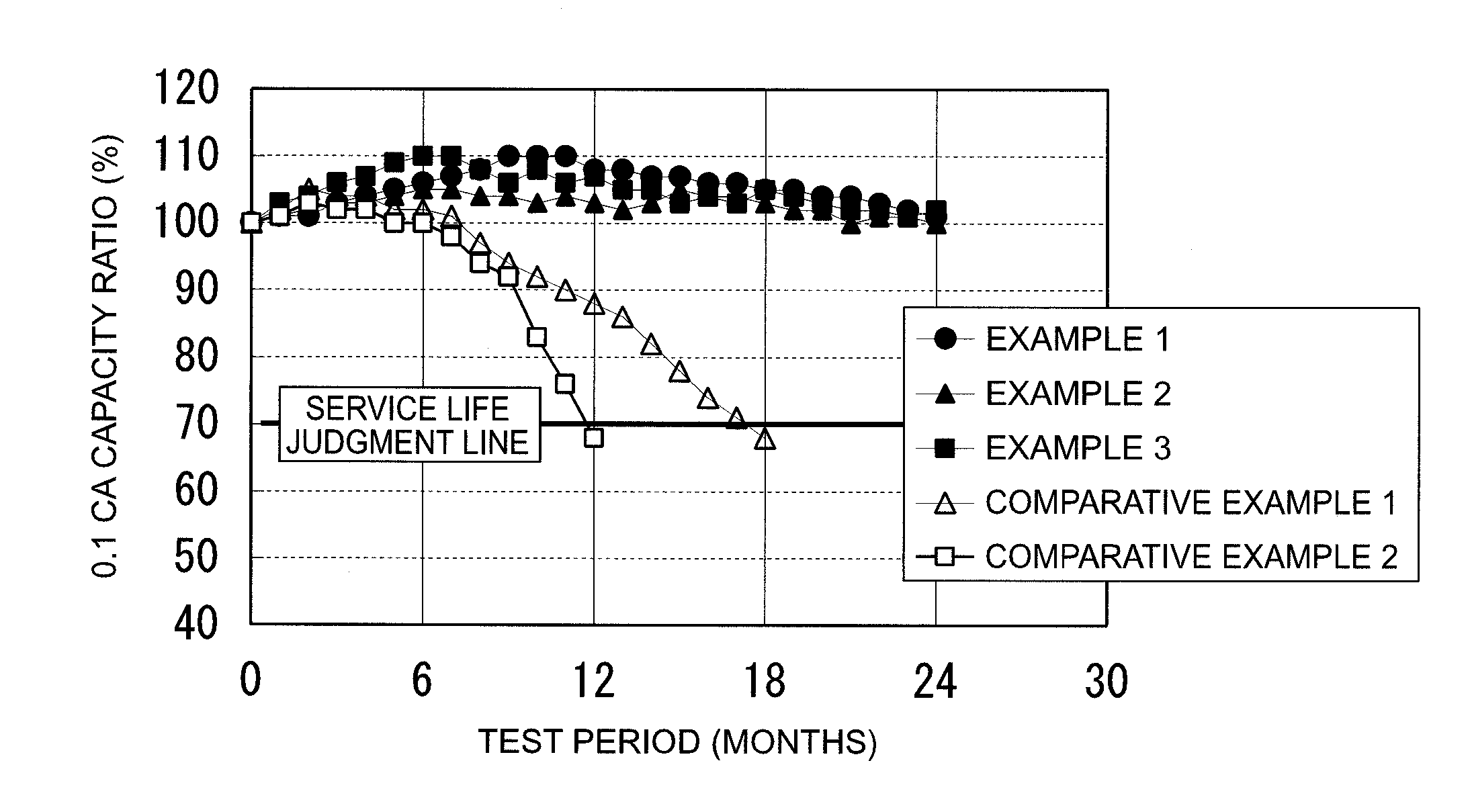
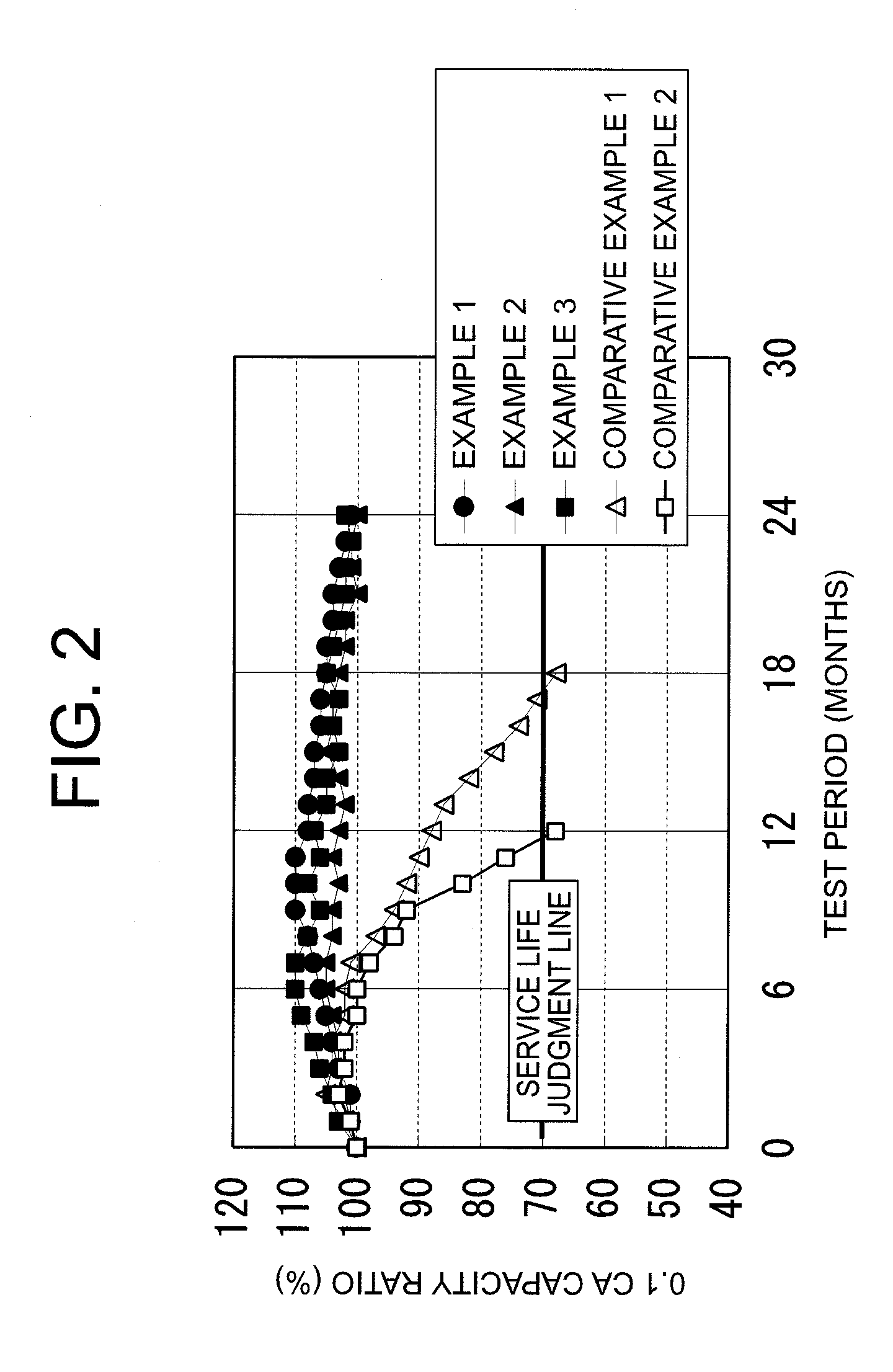
[0101]An operational test was carried out to ascertain the effect of the SOC. In this test, the SOC was 60%, the charge current was 0.2 CA, the discharge current was 0.2 CA, and charging for one second and discharging for one second was repeated without a rest interval. The test was carried out at a temperature of 25° C., the battery voltage was kept in a range of 1.80 V to 2.42 V per cell, and the degree of degradation was compared with other tests. In the present example, the SOC was kept at 60% throughout the interval of the operational test.

example 2

[0102]An operational test was carried out to ascertain the effect of the SOC with the SOC at 30%, the charge current at 0.2 CA, and the discharge current at 0.2 CA. Charging for one second and discharging for one second was repeated without a rest interval. The test was carried out at a temperature of 25° C., the battery voltage was kept in a range of 1.80 V to 2.42 V per cell, and the degree of degradation was compared with other tests. In the present example, the SOC was kept at 30% throughout the interval of the operational test. The only difference between the present example and example 1 was the SOC.

example 3

[0103]An operational test was carried out to ascertain the effect of the SOC with the SOC at 90%, the charge current at 0.2 CA, and the discharge current at 0.2 CA. Charging for one second and discharging for one second was repeated without a rest interval. The test was carried out at a temperature of 25° C., the battery voltage was kept in a range of 1.80 V to 2.42 V per cell, and the degree of degradation was compared with other tests. In the present example, the SOC was kept at 90% throughout the interval of the operational test. The only difference between the present example and example 1 was the SOC.


PUM


Abstract

There is provided a method for operating a lead acid storage battery in order to compensate for fluctuations in the amount of power generated by a solar power generation apparatus, a wind power generation apparatus, or another natural energy power generation device, the lead acid storage battery being charged by a power generation device and discharged to a load. The state of charge of the lead acid storage battery is maintained in a range of 30 to 90% where the fully charged state of the lead acid storage battery is 100%; and the lead acid storage battery is charged and discharged while the battery voltage is kept in a specified range of 1.80 to 2.42 V per cell to extend the service life of the battery. A reference temperature of 25° C. is established, and when the ambient temperature has risen above or fallen below the reference temperature, the upper and lower limit values of a specified range are corrected within a range of −4 mV/° C. to −6 mV/° C. per cell according to the amount by which the temperature has increased or decreased so that a corrected voltage range is obtained. The storage battery is charged and discharged while the battery voltage is kept in the corrected voltage range, and the battery is operated.

Description

TECHNICAL FIELD OF THE INVENTION[0001]The present invention relates to a method for operating a lead acid storage battery disposed in power generation equipment provided with a solar power generation apparatus, a wind power generation apparatus, or another power generation device that uses natural energy; and relates to a storage device provided with a lead acid storage battery operated in accordance with the operation method.PRIOR ART OF THE INVENTION[0002]In recent years, reduction of CO2 emissions has come to be viewed as important to protect the earth's environment and prevent global warming. In view of this goal, loads have come to be driven using solar power generation apparatuses, wind power generation apparatuses, or other power generation devices that use natural energy to generate power (hereinbelow referred to as natural energy power generation devices). For example, it is proposed in Japanese Laid-open Patent Application No. 2004-221521 that electric vehicle batteries ar...

Claims


Application Information

Patent Timeline
IPC IPC(8): H02J7/04H01M10/46
CPCH02J3/32H02J7/0091Y02E10/566Y02E10/766Y02E70/30H01M10/44H02J3/382H01M10/46Y02E10/563H02J3/383H02J3/386Y02E10/763H01M10/448H02J2300/28H02J2300/20H02J2300/24H02J3/381Y02E10/56Y02E10/76Y02E60/10H02J7/007192H02J3/46H02J7/0048H01M10/61H01M10/635H01M10/486H02J7/04H01M2220/10H01M2010/4271H01M10/443H02J7/007194H01M10/425H02J2300/22Y02E10/50Y02E10/70
Inventor SANO, SHINICHIMITANI, KATSURAHIROSE, YOSHIKAZUWAKATABE, HIROYUKISHIMOURA, ICHIRO
Owner SHIN KOBE ELECTRIC MASCH
Why Eureka
Try Eureka