
Planar lighting device

a lighting device and planar technology, applied in the direction of planar/plate-like light guides, lighting and heating apparatus, instruments, etc., can solve the problems of uneven illuminance distribution, decreased light emitted through the light exit plane farther from the light entrance plane, and difficulty in further reducing the thickness of the backlight unit using the direct illumination type backlight uni

Inactive Publication Date: 2011-11-10
FUJIFILM CORP
View PDF3 Cites 16 Cited by
  • Summary
  • Abstract
  • Description
  • Claims
  • Application Information

AI Technical Summary

Benefits of technology

The present invention provides a planar lighting device and a method of producing it that can achieve a high light use efficiency, minimize unevenness in luminance, and guide the admitted light deep into the light guide plate to achieve an even or convex luminance distribution. This is achieved by providing a light guide plate with a light exit plane being rectangular, at least one light entrance plane for admitting light traveling parallel to the light exit plane, and transmittance adjusting members distributed in a given pattern on a side of the light guide plate closer to the rear plane or on both sides. The distribution density of the transmittance adjusting members continuously changes in a way that it decreases with increasing distance from the light entrance plane and increases with the increasing distance. The light guide plate may contain scattering particles dispersed therein and the light exit plane may be concave or convex. The invention also provides a method for producing a light guide plate with a high light use efficiency and minimized unevenness in luminance.

Problems solved by technology

To achieve a uniform light amount distribution with a direct illumination type backlight unit, however, a thickness of about 30 mm in a direction normal to the liquid crystal display panel is required, making further reduction of thickness of the backlight unit difficult using the direct illumination type backlight unit.
However, when a backlight unit of a type having a pattern formed on a surface opposite, for example, from the light exit plane, is to be made thinner and larger, guiding the admitted light deep into the light guide plate becomes difficult, so that the amount of light emitted through the light exit plane farther from the light entrance plane decreases, producing uneven illuminance distribution (luminance distribution) while reducing the light use efficiency.
Further, when a backlight unit is to be made thinner and larger, the pattern distribution density needs to be reduced in order to guide the admitted light deep into the light guide plate, whereas when the pattern distribution density is small, the admitted light is not diffused sufficiently near the light entrance plane, so that the light leaving the light exit plane may develop visible bright lines (dark lines, unevenness), which are attributable to such causes as space intervals at which the light source units of the light source are disposed, near the light entrance plane.

Method used


Image

  • Planar lighting device
  • Planar lighting device
  • Planar lighting device

Examples


example 1

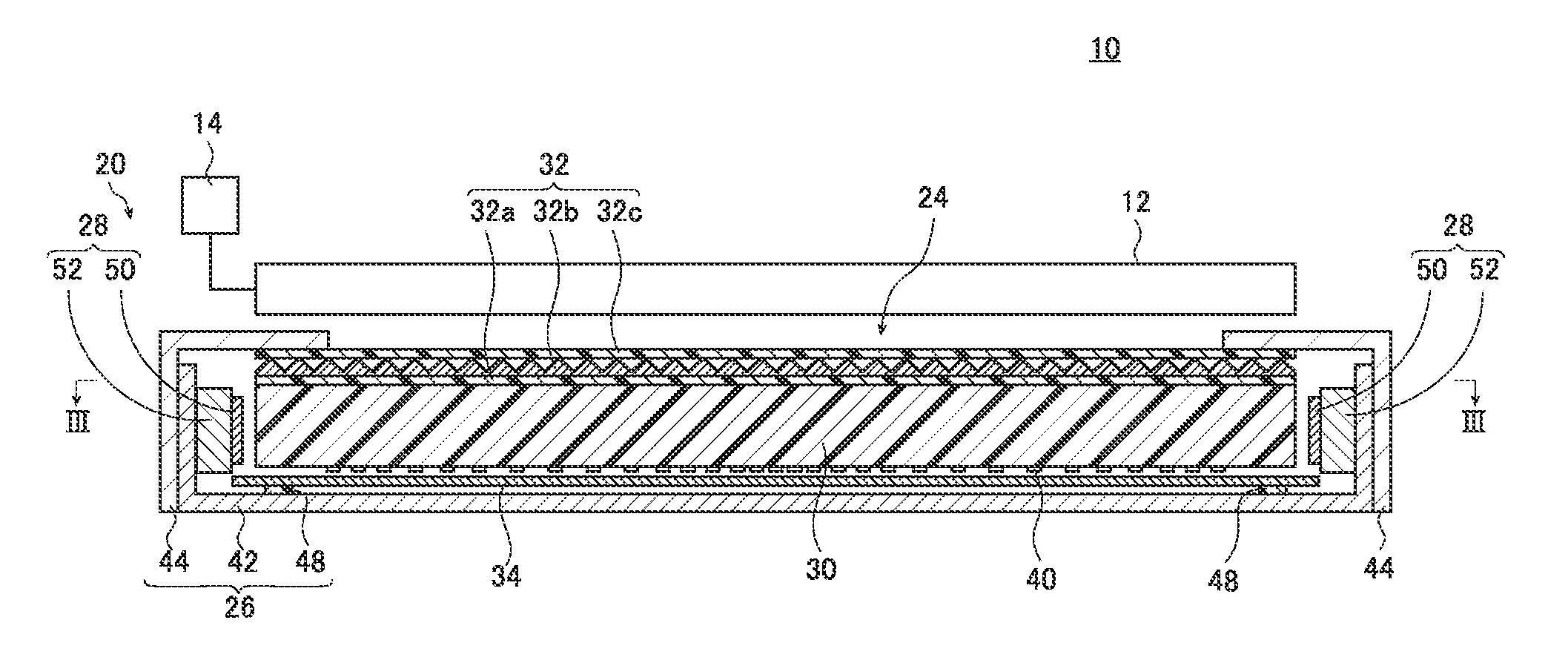
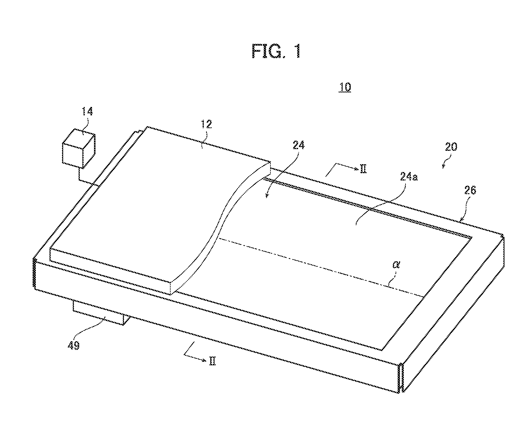
The backlight unit 20 used in an example 1 had dimensions corresponding to a 40-inch screen. The emission surface of the backlight unit 20 corresponding to a 40-inch screen has a length of 499 mm in the direction normal to the light entrance planes.

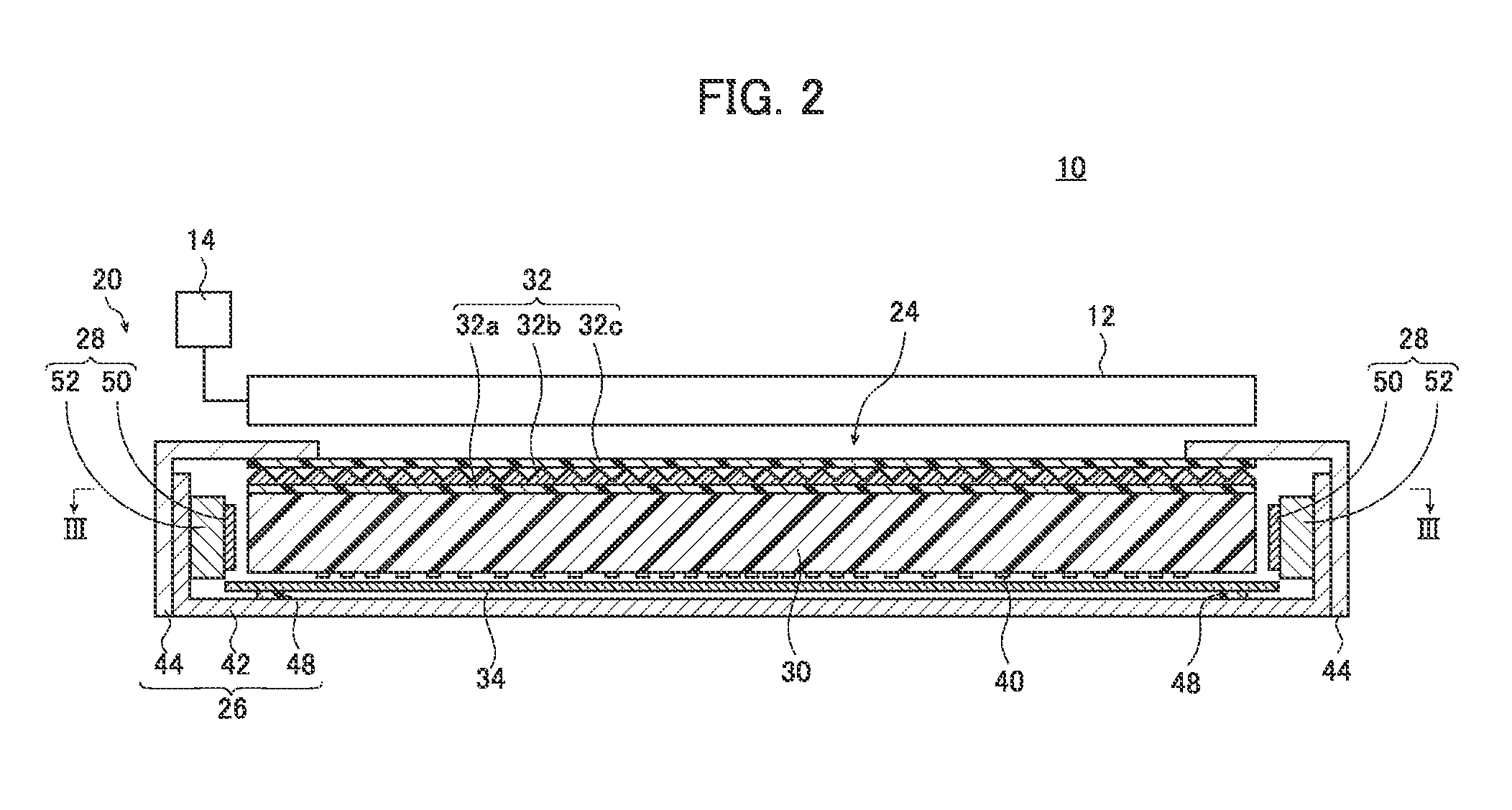
Specifically, a model of the light guide plate 30 used in the simulation was a flat light guide plate made of a base material PMMA containing silicone scattering particles kneaded and dispersed therein. The light guide plate 30 was 1 mm thick; the scattering particles had a diameter of 4.5 μm.

A model of the light source 28 comprised LED chips each measuring 1.5 mm×2.6 mm arrayed at a pitch of 7 mm. For easy comparison, the simulation used only one light source 28, admitting light only through the first light entrance plane 30d and not admitting light through the second light entrance plane 30e.

The transmittance adjusting members 40 were provided by forming concave dots having a diameter of 0.05 mm on the rear side 30b of the light guide ...

example 12

where the light guide plate had a length of 539 mm and a marginal region length L of 20 mm;

example 13

where the light guide plate had a length of 549 mm and a marginal region length L of 25 mm;


PUM


Abstract

A planar lighting device using a large and thin light guide plate and yet capable of yielding a high light use efficiency, emitting light with a minimized unevenness in luminance, and guiding the admitted light deep into the light guide plate to achieve a uniform or convex luminance distribution, i.e., a distribution curve that is high in a range near the middle of the screen as compared with the peripheral area of the screen. The light guide plate is provided on its rear side, or on the side thereof closer to the light exit plane, or on both sides in a given pattern with a distribution density changing continuously so as to once decrease with the increasing distance from the light entrance plane, and then increase with the increasing distance.

Description

BACKGROUND OF THE INVENTIONThe present invention relates to a planar lighting device used for a liquid crystal display device and the like.Liquid crystal display devices use a backlight unit for radiating light from behind the liquid crystal display panel to illuminate the liquid crystal display panel. A backlight unit is configured using a light guide plate for diffusing light emitted by an illumination light source to irradiate the liquid crystal display panel and optical parts such as a prism sheet and a diffusion sheet for rendering the light emitted from the light guide plate uniform.Currently, large liquid crystal televisions predominantly use a so-called direct illumination type backlight unit comprising a light guide plate disposed immediately above the illumination light source. This type of backlight unit comprises a plurality of cold cathode tubes serving as a light source provided behind the liquid crystal display panel whereas the inside of the backlight unit provides w...

Claims


Application Information

Patent Timeline
Patent Type & Authority Applications(United States)
IPC IPC(8): F21V8/00
CPCG02B6/0036G02B6/0061G02B6/0091G02B6/0073G02B6/0068
Inventor IWASAKI, OSAMU
Owner FUJIFILM CORP
Learn More