
Screen area detection method and screen area detection system

Inactive Publication Date: 2011-11-10
RICOH KK
View PDF9 Cites 26 Cited by
  • Summary
  • Abstract
  • Description
  • Claims
  • Application Information

AI Technical Summary

Benefits of technology

[0010]In order to solve the above described problems in the conventional techniques, in the present invention, a method, of accurately obtaining whiteboard sides in a system adopting a computer-human interaction virtual whiteboard so as to obtain an accurate coordinate position of a pointing spot projected on a screen with regard to the screen, is provided so that it is possible to output the accurate coordinate position of the pointing spot with regard to the screen to the system adopting the computer-human interaction virtual whiteboard so as to able to use the pointing spot to carry out interactions with a computer.
[0019]As a result, by obtaining the four boundaries of the screen area, it is possible to output coordinates of respective corner points of the screen area.
[0023]According to the embodiments of the present invention, by using the above described screen area detection method to obtain the accurate coordinates of the respective corner points with regard to the detected screen area, it is possible to convert coordinates of a pointing spot with regard to the captured image into coordinates of the pointing spot with regard to the detected screen area. In general, the accuracy of the converted coordinates of the pointing spot with regard to the detected screen area depends very much on the accuracy of the screen area detection. Since the accurate coordinates of the respective corner points with regard to the detected screen area can be obtained according to the embodiments of the present invention, it is possible to obtain a high-accuracy position of the pointing spot in the detected screen area.

Problems solved by technology

As a result, it is difficult to carry out screen area detection in the captured image by using conventional techniques; in other words, it is difficult to use, for example, a general-purpose corner point detection algorithm to obtain an accurate result.

Method used


Image

  • Screen area detection method and screen area detection system
  • Screen area detection method and screen area detection system
  • Screen area detection method and screen area detection system

Examples


Embodiment Construction

[0033]Hereinafter, various embodiments of the present invention will be concretely described with reference to the drawings. Here it should be noted that the same symbols, which are in the specification and the drawings, stand for constructional elements having the same or basically-same function and structure, and repeated explanations for the constructional elements are omitted in the specification.

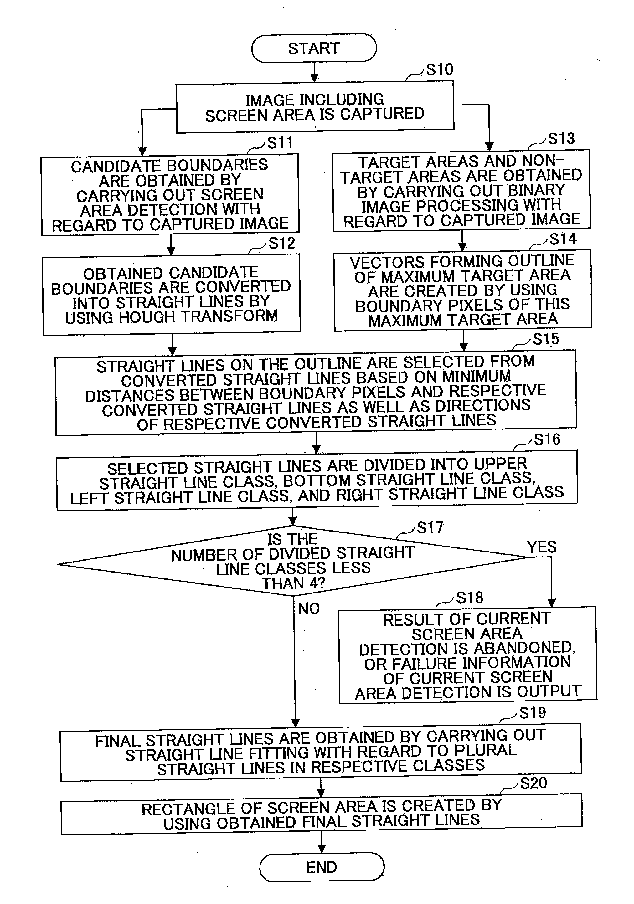
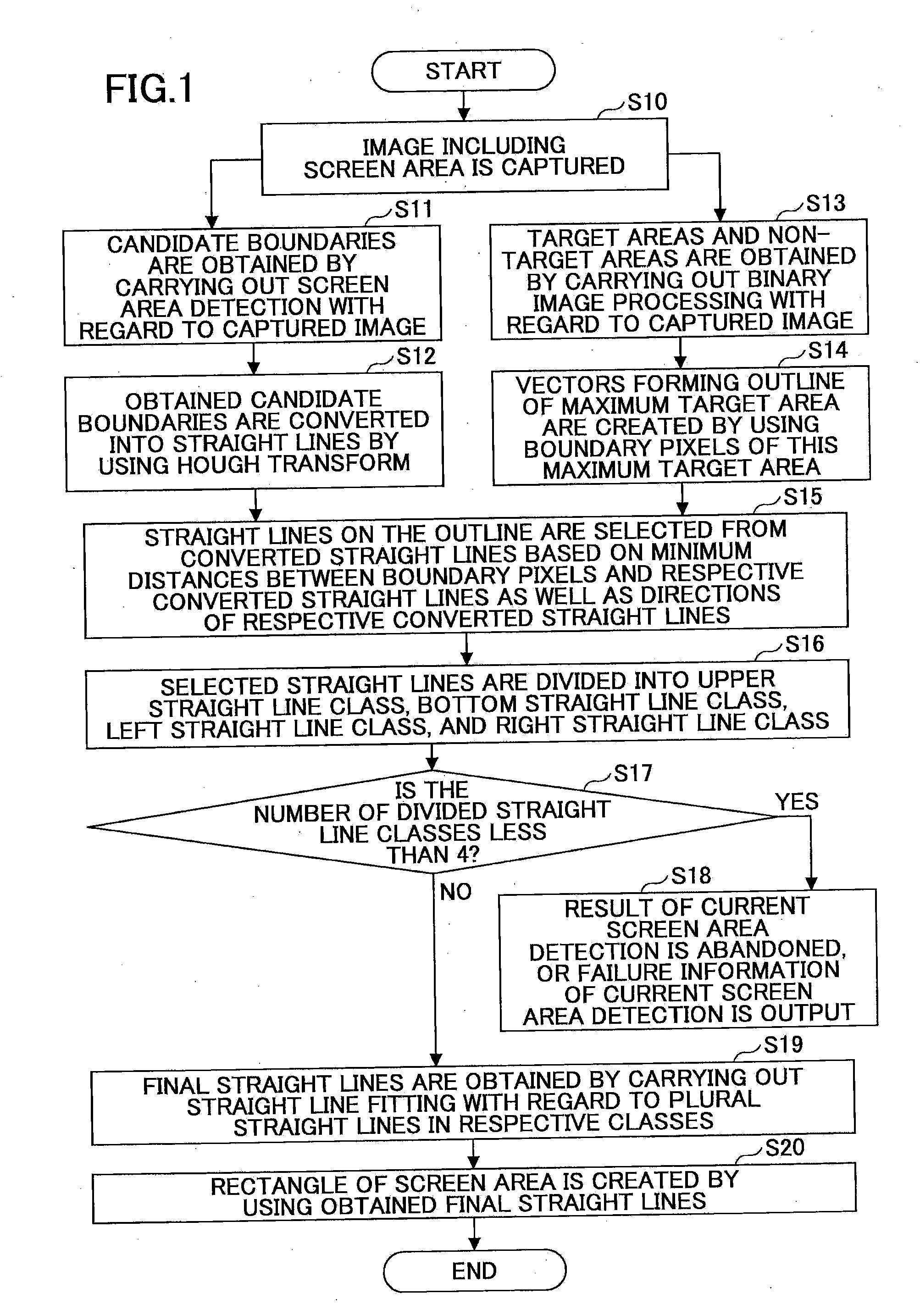
[0034]FIG. 1 is a flowchart of a screen area detection method according to an embodiment of the present invention.

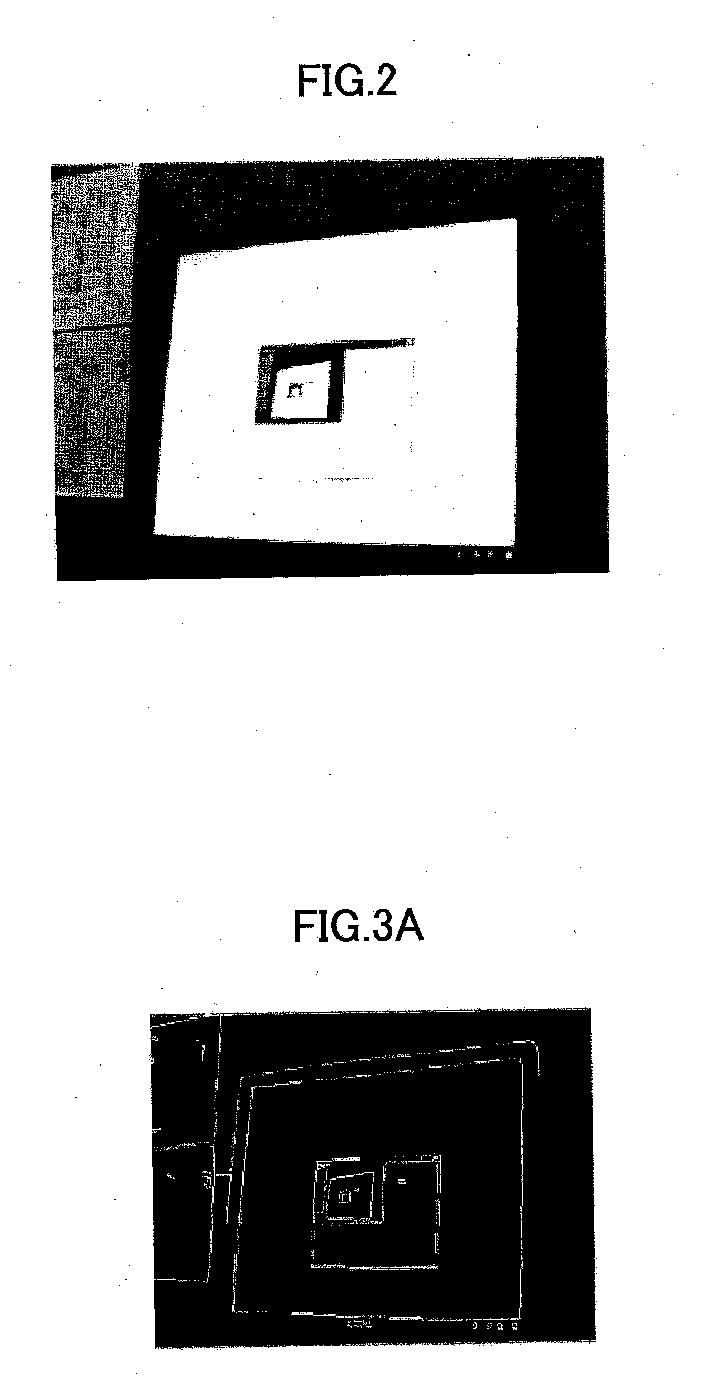
[0035]As shown in FIG. 1, first, in STEP S10, an image capture device captures an image (i.e. a frame) including a screen area as shown in FIG. 2, and outputs the captured image to a computer such as a computer 501 shown in FIG. 5 so as to carry out follow-on processing. This kind of image capture device may be a camera 503 as shown in FIG. 5. An image shown in FIG. 2 is a 256-level grayscale image including a computer screen. However, this is only an example; it is possible...


PUM


Abstract

Disclosed are a method and a system for detecting a screen area. The method comprises a step of capturing an image including the screen area; a step of obtaining candidate boundaries of the screen area; a step of converting the candidate boundaries into straight lines; a step of carrying out binary image processing with regard to the captured image; a step of obtaining boundary pixels of a maximum target area, and letting the boundary pixels serve as an outline of the maximum target area; a step of selecting straight lines on the outline from the converted straight lines; a step of dividing the selected straight lines into four classes; and a step of obtaining final straight lines by carrying out straight line fitting with regard to straight lines in the respective classes so as to obtain four boundaries of the screen area.

Description

BACKGROUND OF THE INVENTION[0001]1. Field of the Invention[0002]The present invention relates to the field of image processing, particularly relates to the field of image division, and more particularly related to a method of detecting a screen area in a captured image as well as a system using the method.[0003]2. Description of the Related Art[0004]In various meetings, it is very helpful to use a projector as an assistant tool for a presentation. However, during the presentation, a presenter needs to frequently operate a computer to switch contents needing to be projected on a screen, or needs to let an assistant switch the contents projected on the screen by operating a computer connected to the projector according to presentation speed of the presenter. This kind of method of using the projector brings ultra-convenience to the presenter, but its operation still costs time or work.[0005]As a result, a method able to operate a computer by directly clicking contents on a screen has ...

Claims


Application Information

Patent Timeline
IPC IPC(8): G06K9/34
CPCG06K9/00664G06T2207/20136G06T2207/20061G06T7/0083G06T7/12G06T7/181G06V20/10
Inventor YU, HAILONGLI, DONGLAIZHANG, WENBOPAN, PINGPINGGONG, WEITAO
Owner RICOH KK
Learn More