Refrigerant leak detection system

a leak detection and refrigerant technology, applied in lighting and heating apparatus, heating types, instruments, etc., can solve the problems of reducing the concentration of refrigerant, and affecting the operation of the system

Inactive Publication Date: 2011-11-17
MAHLE INT GMBH
View PDF9 Cites 35 Cited by
  • Summary
  • Abstract
  • Description
  • Claims
  • Application Information

AI Technical Summary

Benefits of technology

[0008]An embodiment of the present invention provides for a refrigerant leak detection system for a motor vehicle. The system includes an HVAC module having a refrigerant sensor assembly disposed within a low-lying portion of the HVAC module, preferably within the condensate sump, to detect refrigerants having a vapor density heavier than air. Preferably, the refrigerant sensor assembly is fixedly inserted into the drain hole of the condensate sump for ease of access. The refrigerant sensor assembly includes an elongated sensor element extending above any accumulated condensate within

Problems solved by technology

If a leak occurs in the air conditioning system within the hood of the motor vehicle, the heavier refrigerant vapor would settle to the lowest point within the engine compartment and dissipates to the environment.
However, if a leak occurred within the evaporator or a portion of the refrigerant line that is contained within the HVAC module, the heavier vapors could potentially be dispersed into the passenger compartment.
For small leaks, the large amount of air flow may dilute the c

Method used


Image

  • Refrigerant leak detection system
  • Refrigerant leak detection system
  • Refrigerant leak detection system

Examples


Embodiment Construction

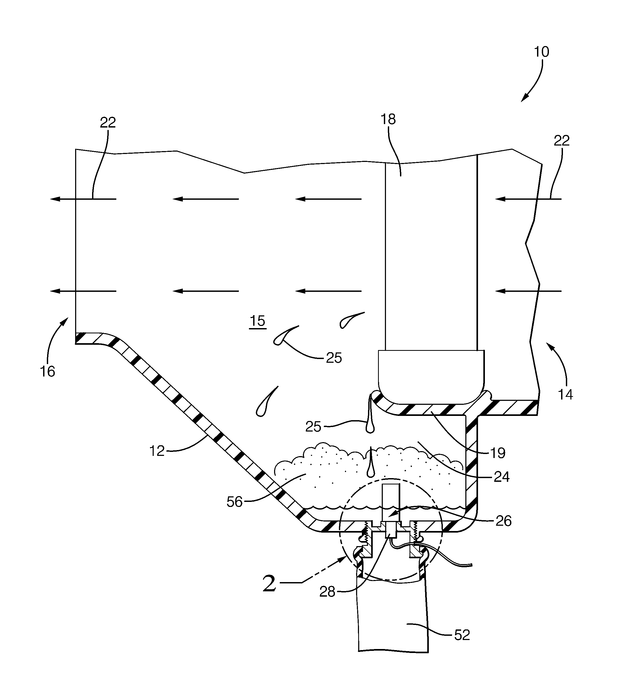
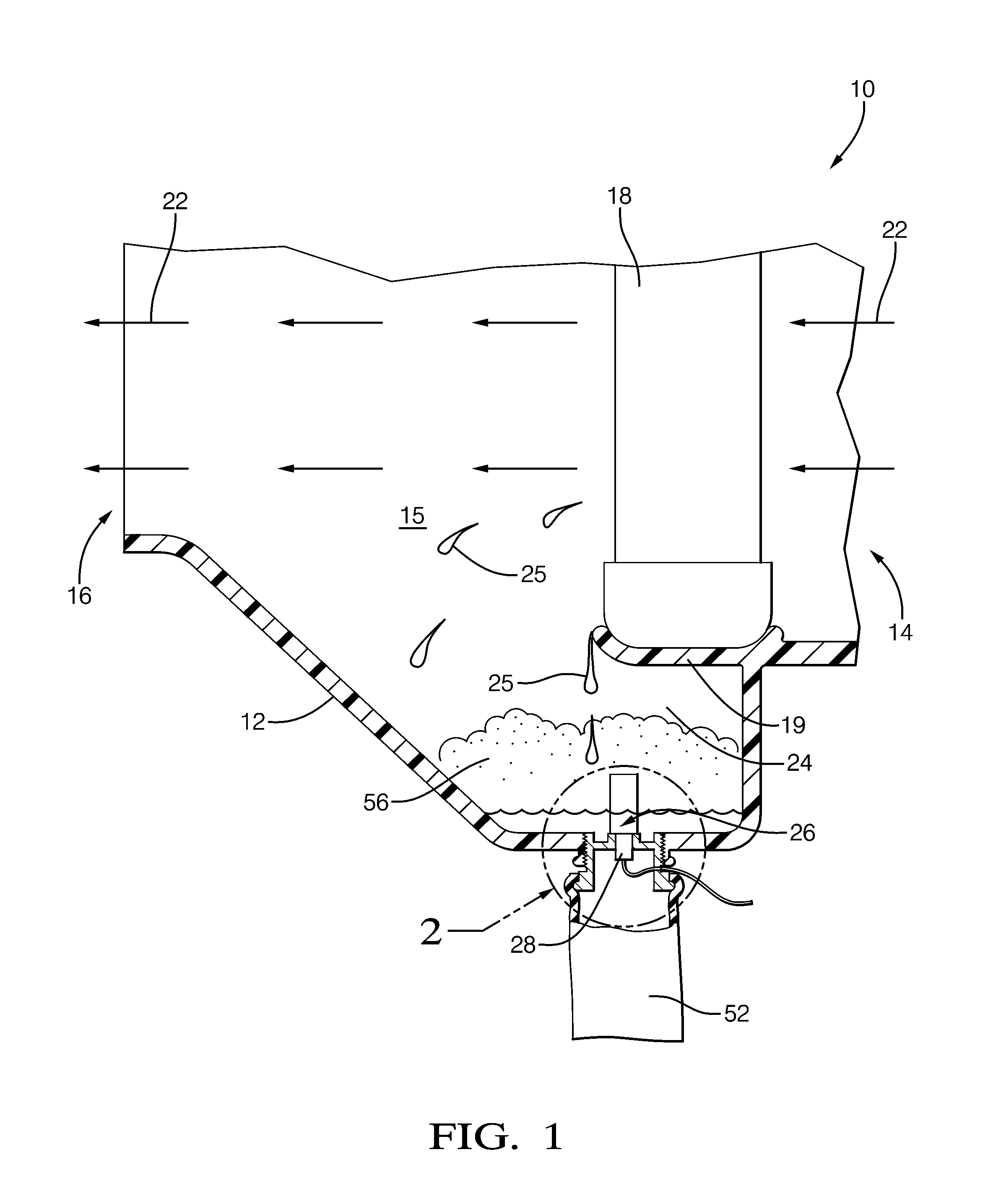
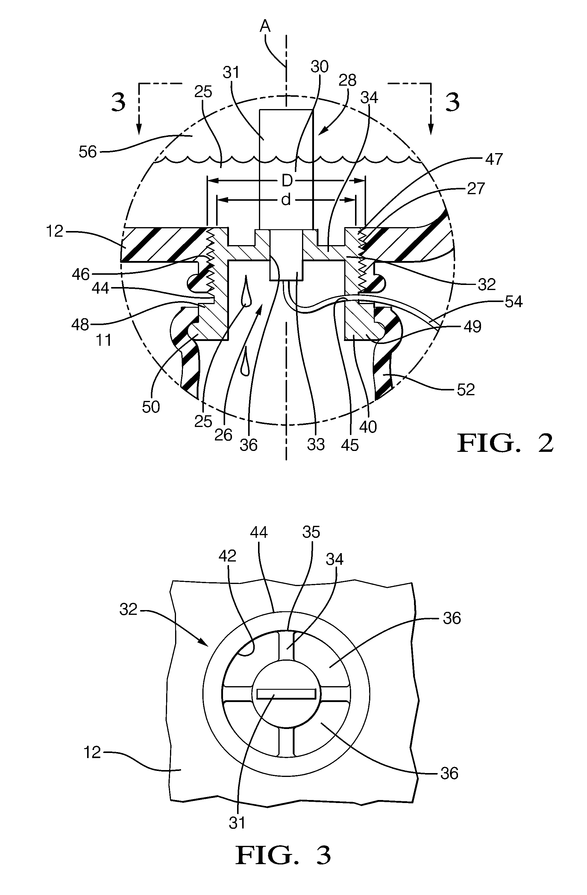
[0015]In accordance with a preferred embodiment of this invention, referring to FIGS. 1 through 3 is a refrigerant leak detection system 10 that includes a heating, ventilating, and air conditioning (HVAC) module 12 having a condensate sump 24 with a drain hole 26 and a refrigerant sensor assembly 28 positioned within the drain hole 26. The refrigerant sensor assembly 28 is adapted to fixedly engage itself within the drain hole 26 of the HVAC module 12 and to allow for drainage of condensate from the condensate sump 24.

[0016]A typical HVAC module 12 includes an air inlet 14 for drawing in unconditioned air, a labyrinth of passageways 15 for directing air flow throughout the HVAC module 12, and an air outlet 16 for distributing conditioned air to the passenger compartment. Air flow doors (not shown) are positioned at strategic junctures through the passageways 15 in order to selectively direct and proportion an amount of air flow to heat exchangers within the HVAC module 12 to contro...


PUM


Abstract

A refrigerant leak detection system is provided for a motor vehicle, in which the system includes a heating, ventilating, and air conditioning (HVAC) module having a refrigerant sensor assembly adapted to be fixed within the drain hole of the sump. The refrigerant sensor assembly includes an elongated sensor element extending into the sump, a flange portion having apertures that allows the condensate to drain from sump, a collar portion with self-tapping threads.

Description

CROSS REFERENCE TO RELATED APPLICATION[0001]This application claims the benefit of U.S. Provisional Patent Application Ser. No. 61 / 117,992 for a REFRIGERANT DETECTION SYSTEM, filed on Nov. 26, 2008, which is hereby incorporated by reference in its entirety. This claim is made under 35 U.S.C. §119(e); 37 C.F.R. §1.78; and 65 Fed. Reg. 50093.TECHNICAL FIELD OF INVENTION[0002]The invention relates to a refrigerant leak detection system for a motor vehicle; more particularly to a HVAC module having a refrigerant sensor assembly for detecting refrigerant vapors that are heavier than air.BACKGROUND OF INVENTION[0003]A typical motor vehicle air conditioning system includes a compressor, a condenser, an expansion device, and an evaporator. The condenser is disposed in the front portion of the engine compartment or more precisely, in front of the radiator exposed to the outside ambient air. The evaporator is disposed within a heating, ventilating, and air conditioning (HVAC) module that cond...

Claims


Application Information

Patent Timeline
IPC IPC(8): G01M3/20
CPCB60H1/00978F24F2011/0084F24F11/001B60H1/3233F24F11/30F24F2110/00F24F11/36
Inventor KADLE, PRASAD S.GHODBANE, MAHMOUD
Owner MAHLE INT GMBH
Why Eureka
Try Eureka