
Apparatus Having a Roughness Measurement Sensor and Corresponding Methods

a technology of roughness measurement and sensors, applied in the direction of mechanical roughness/irregularity measurement, measurement devices, instruments, etc., can solve the problems of different runner sensors being visible, and runner sensors being also susceptible to falsification

Active Publication Date: 2011-11-17
KLINGELNBERG AG
View PDF15 Cites 13 Cited by
  • Summary
  • Abstract
  • Description
  • Claims
  • Application Information

AI Technical Summary

Benefits of technology

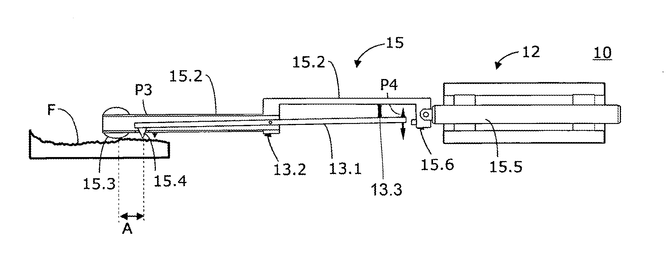
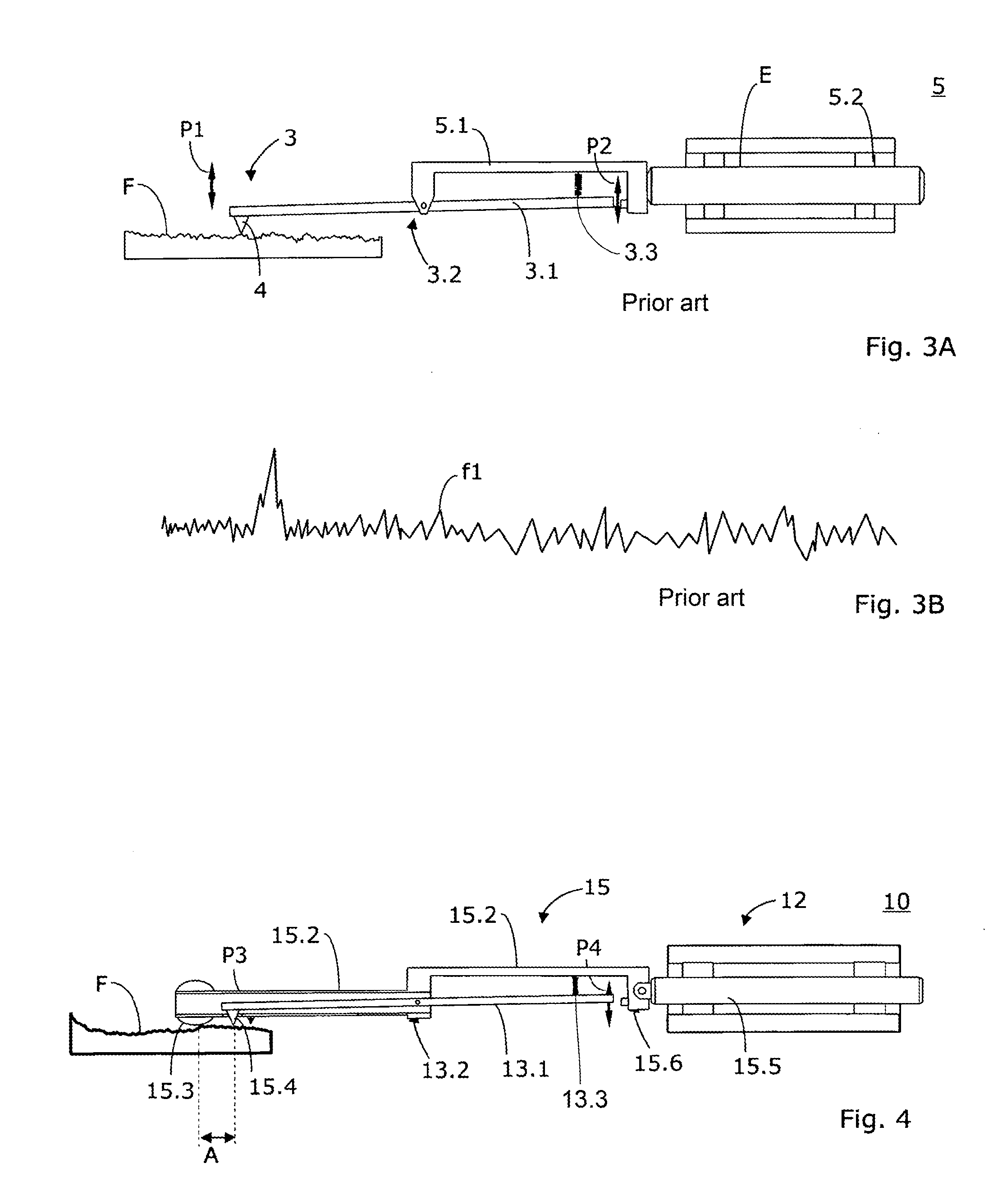
The invention is a measurement apparatus that includes a roughness sensing system and a roughness measurement sensor. The apparatus allows for improved roughness measurements and can conduct measurements at specific positions on identical constructional elements. The apparatus also allows for easy replacement of the roughness measurement sensor without the need for a new calibration after each exchange. The apparatus includes a scan-slide element and a probe tip that move jointly over a surface being scanned. The scan-slide element has a unique shape that is not necessarily ideal spherical, and can be designed with different radii in the axial and radial direction. The apparatus can collect information about a surface that is comparable or better than a reference plane sensor, and can also collect the deviation of the movement of the scan-slide element from an ideal straight line or reference plane. The invention can be used in connection with 1D-, 2D- and 3D-measurement apparatuses.

Problems solved by technology

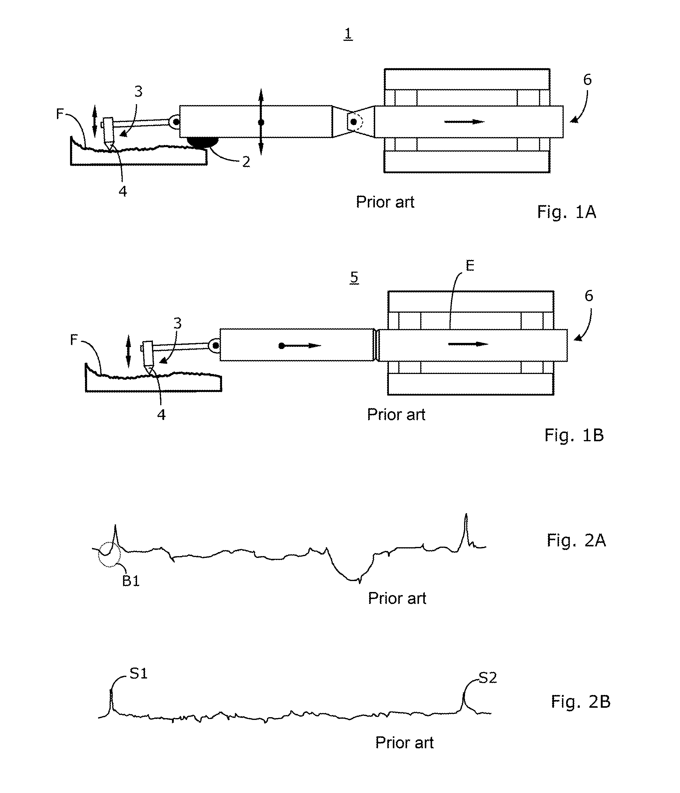
In particular, in the case of deep grooves or of isolated high peaks S1 and S2 (see FIG. 2B), the errors of the different runner sensors become noticeable.
However, a runner sensor may also yield falsified results in other situations.
These problems occur for example for periodic surfaces.

Method used


Image

  • Apparatus Having a Roughness Measurement Sensor and Corresponding Methods
  • Apparatus Having a Roughness Measurement Sensor and Corresponding Methods
  • Apparatus Having a Roughness Measurement Sensor and Corresponding Methods

Examples


Embodiment Construction

[0039]In relation with the present description, terms are used that are conventional to pertinent publications and patents. It is noted however that the use of these terms are only for descriptive purposes and should not be construed as limiting. The inventive idea and the scope of the patent claims shall not be limited in their interpretation by the specific choice of the terms used in the specification. The invention can be adapted to other systems of terminology and / or technical fields. In other technical fields, the terms are to be used analogously.

[0040]The term roughness is used here to denominate the surface quality of a surface. The roughness is limited to microscopic dimensions, in the sense of particular points or local conditions. Herein, typically in relation with the roughness, structures, elements and features of a surface F are concerned that have a size in the range of nm to approximately 500 μm.

[0041]A shape (also termed evenness) is a 2- or 3-dimensional plane or a...


PUM


Abstract

An apparatus having a roughness sensing system and a roughness measurement sensor, wherein a slide element and a probe tip come to operation, and method of use thereof. The slide element is arranged on an extreme end of a probe pin in the form of a scan-slide element. The probe tip is integrated into the probe pin, and the distance between the scan-slide element and the probe tip is predetermined. The roughness sensing system is a 1D-, 2D- or 3D-scanning system having a parallelogram configuration. The apparatus further has a serving device which enables moving the probe pin together with the scan-slide element and the probe tip jointly over a surface to be scanned.

Description

CROSS-REFERENCE TO RELATED APPLICATIONS[0001]This application is a continuation of International Patent Application No. PCT / EP2009 / 066323, filed Dec. 3, 2009, designating the United States, and claims priority under 35 U.S.C. §119(a)-(d) to European Patent Application No. EP 08172410.6, filed Dec. 19, 2008, the contents of both of which are hereby incorporated by reference in their entirety as part of the present disclosure.FIELD OF THE INVENTION[0002]The invention relates to apparatuses comprising roughness measurement sensors, and corresponding methods.BACKGROUND OF THE INVENTION[0003]In many technical areas, the surface structure of a constructional element or a material is an important quality characteristic.[0004]There are different roughness measurement devices for rapidly collecting the roughness and / or scallop height of surfaces. Typically, during a mechanical scanning, a probe tip is guided over the surface. The result is a height signal recorded over the scanning path, the...

Claims


Application Information

Patent Timeline
Patent Type & Authority Applications(United States)
IPC IPC(8): G01B5/28
CPCG01B5/28
Inventor MIES, GEORG
Owner KLINGELNBERG AG
Learn More