Pneumatic tire

a pneumatic tire and tire body technology, applied in the field of pneumatic tires, can solve the problems of decreasing the overall the decline of the increase of the number of edges, so as to achieve the effect of enhancing the braking performance on ice, preventing the excessive collapsing of the portions of the block, and maintaining the rigidity of the block roughly uniformly

Inactive Publication Date: 2011-11-17
THE YOKOHAMA RUBBER CO LTD
View PDF8 Cites 16 Cited by
  • Summary
  • Abstract
  • Description
  • Claims
  • Application Information

AI Technical Summary

Benefits of technology

[0010]The present technology was devised in light of the problems described above and provides a pneumatic tire that is useful in suppressing excessive rigidity and enhancing braking performance on ice even when the wearing of the block has progressed.
[0011]The technology also provides a pneumatic tire that enhances braking performance on ice and is useful for suppressing the collapse of portions of blocks positioned in areas that partition sipes in the longitudinal direction of the sipes, which areas are more prone to collapse compared to other areas.
[0014]With the technology, when a tire is new, the protrusions that protrude a large amount engage with the recesses. Therefore, the collapsing of the portions of the block that partition the sipes is suppressed and braking performance on ice is enhanced. Additionally, after the tire is worn, since rigidity of the portions of the block increases, next the protrusions that protrude a small amount engage with the recesses. Therefore, the suppression of the collapsing of the portions of the block is prevented from becoming excessive, the rigidity of the block is roughly uniformly maintained from when the tire is new through to after it is worn, and braking performance on ice is maintained.
[0015]Moreover, with the technology, since the portions of the block collapse uniformly in the longitudinal direction of the sipes, a bottom-raising effect in the area of the portions of the block that are prone to collapsing can be obtained, and a decline of the rigidity of the block can be suppressed when the tire is worn without reducing the number of sipe edges. Therefore, braking performance on ice is enhanced.

Problems solved by technology

However, sipe density is increased as a result of increasing the number of sipes, and while this leads to an increase in the number of edges, it also leads to the problems of the overall rigidity of the block declining and braking performance on ice declining.
However, an issue still remains because, as wearing of the block progresses, a height of the portions of the block that are sandwiched by the sipes is reduced, and, moreover, rigidity becomes excessive as a result of suppressing the collapsing of the portions of the block by means of the recesses and protrusions.
Additionally, from a perspective of the rigidity of the block, the portions of the block, which are sandwiched by the sipes, located at the edges of the block in the tire width direction are prone to collapse.
Moreover, from a perspective of the rigidity of the portions of the block, if a length of the sipes is great, the portions of the block located in a central region in the longitudinal direction will be prone to collapse.
Thus, when there are portions of the block in the longitudinal direction of the sipes that are more prone to collapse compared with other areas, it is difficult to enhance the edge effect.

Method used


Image

  • Pneumatic tire
  • Pneumatic tire
  • Pneumatic tire

Examples


first embodiment

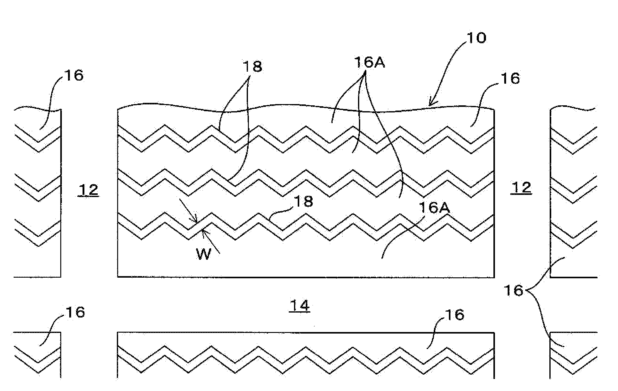
[0024]As illustrated in FIGS. 1 and 2, a plurality of vertical grooves 12 extending in a tire circumferential direction and a plurality of lateral grooves 14 that intersect with the vertical grooves 12 are provided in a tread surface 10. Additionally, a land portion provided with a block 16 is provided in the tread surface 10.

[0025]Moreover, a plurality of sipes 18 extending in a tire width direction is provided in the tread surface 10 of the block 16 (land portion).

[0026]A plurality of portions 16A of the block 16 sandwiched by the sipes 18 and portions 16A of the block 16 sandwiched by the sipes 18 and the lateral grooves 14 are positioned on the tread surface 10 side of the block 16 due to the plurality of sipes 18. In other words, these portions 16A of the block 16 partition the sipes 18.

[0027]In order to exert edge effect effectively, a width W of the sipes 18 is preferably 0.3 mm or greater but 1.5 mm or less.

[0028]As illustrated in FIG. 1A, a shape in the longitudinal directi...

example 1

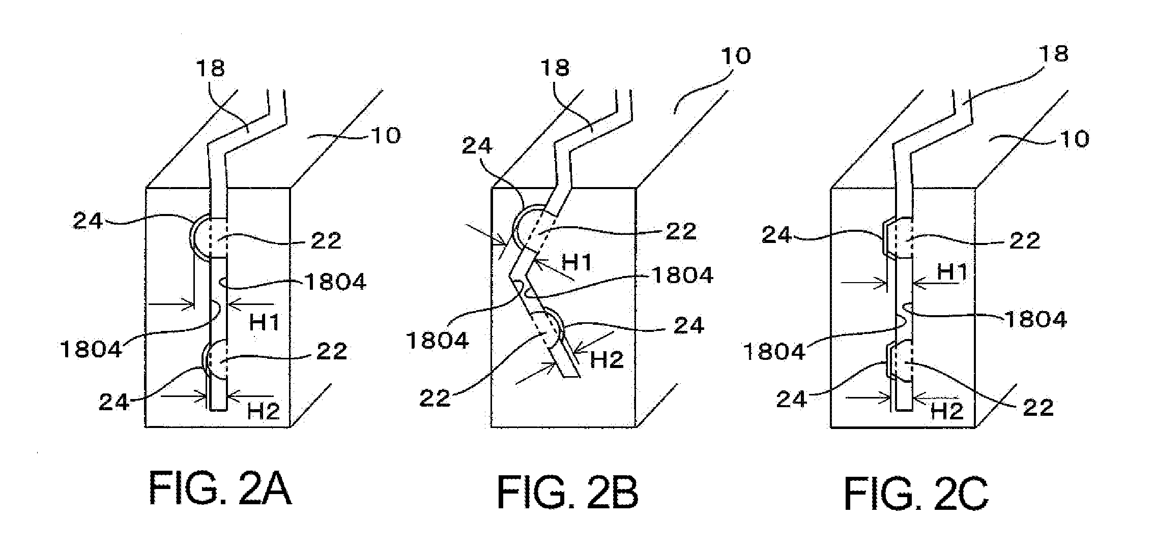
[0041]Radial studless tires having a tire size of 195 / 65R15 provided with protrusions 22 having the configurations shown in FIG. 3 and recesses 24 that engage with these protrusions 22 were assembled on rims having a rim size of 15×6J. The tires were inflated to an inner pressure of 200 kPa and mounted on the four wheels of an RV vehicle having an engine displacement of 2,000 cc. Tests for a Conventional Example and Working Examples 1, 2, 3 and 4 were conducted for dry braking, braking on ice, and braking on ice when the tire is 50% worn.

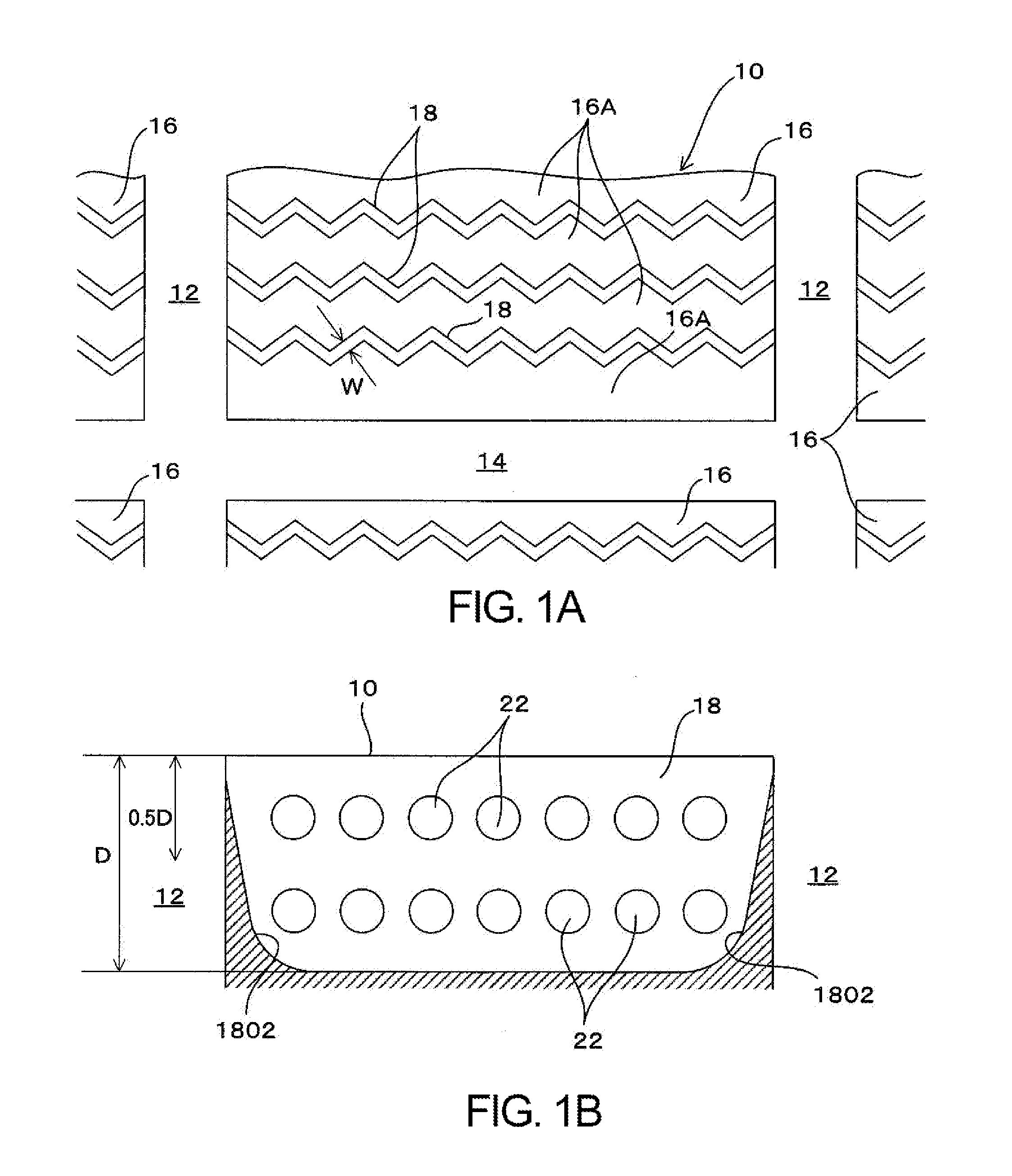
[0042]Note that the width W of the sipes 18 was 0.4 mm, the depth D was 6 mm, and the length L was 10 mm.

[0043]Additionally, the upper portion protrusions 22 were positioned at a depth 2 mm from the tread surface 10, and the lower portion protrusions 22 were positioned at a depth 4 mm from the tread surface 10.

[0044]Dry braking was measured as a braking distance from a point of brake application to stop when travelling on a dry asphalt road surface ...

second embodiment

[0048]As illustrated in FIGS. 4 and 5, a plurality of vertical grooves 12 extending in a tire circumferential direction and a plurality of lateral grooves 14 that intersect with the vertical grooves 12 are provided in a tread surface 10. Additionally, a land portion provided with a block 16 is provided in the tread surface 10.

[0049]Moreover, a plurality of sipes 18 extending in a tire width direction is provided in the tread surface 10 of the block 16 (land portion).

[0050]A plurality of portions 16A of the block 16 sandwiched by the sipes 18, and portions 16a of the block 16 sandwiched by the sipes 18 and the lateral grooves 14 are positioned on the tread surface 10 side of the block 16 due to the plurality of sipes 18. In other words, these portions 16A of the block 16 partition the sipes 18.

[0051]In order to exert edge effect effectively, a width W of the sipes 18 is preferably 0.3 mm or greater but 1.5 mm or less.

[0052]As illustrated in FIG. 4A, a shape in the longitudinal direct...


PUM


Abstract

A plurality of sipes extending in a tire width direction are provided in a tread surface of a block. In the sipes, protrusions are formed on a first sipe wall surface of mutually opposing sipe wall surfaces and recesses that engage with the protrusions are formed on a second sipe wall surface. Collapse of portions of the block sandwiched by the sipes is suppressed due to engagement of the protrusions and the recesses. A height of protrusions positioned on an upper portion in the depth direction of the sipes is greater than a height of protrusions positioned on a lower portion.

Description

PRIORITY CLAIM[0001]Priority is claimed to Japan Patent Application Serial No. 2010-108963 filed on May 11, 2010 and Japan Patent Application Serial No. 2011-095800 filed on Apr. 22, 2011.BACKGROUND[0002]1. Technical Field[0003]The technology relates to a pneumatic tire and particularly relates to a pneumatic tire having enhanced tire braking performance on ice.[0004]2. Related Art[0005]Tread patterns in which a plurality of sipes is disposed in a tire pattern in order to enhance braking performance on ice of studless tires are known. Also, in recent years, there has been a tendency toward increasing the number of sipes. However, sipe density is increased as a result of increasing the number of sipes, and while this leads to an increase in the number of edges, it also leads to the problems of the overall rigidity of the block declining and braking performance on ice declining.[0006]Therefore, technology has been proposed in which collapsing of portions of a block that are sandwiched...

Claims


Application Information

Patent Timeline
Patent Type & Authority Applications(United States)
IPC IPC(8): B60C11/12
CPCB60C11/1218B60C2011/1213Y10S152/03B60C2011/1254B60C11/1259
Inventor NAGAYASU, MASAAKI
Owner THE YOKOHAMA RUBBER CO LTD
Why Eureka
Try Eureka