Laser drilling method and system

a laser drilling and laser technology, applied in laser beam welding apparatus, lasers, stone-like material working apparatus, etc., can solve the problems of limited practical implementation of minimal power required, and uncommercialized laser drilling in wells

Active Publication Date: 2011-11-17
FACULDADES CATOLICAS MANTENEDORA DA PONTIFICIA UNIV CATOLICA DO RIO DE JANEIRO - PUC RIO
View PDF4 Cites 22 Cited by
  • Summary
  • Abstract
  • Description
  • Claims
  • Application Information

AI Technical Summary

Benefits of technology

[0026]Broadly, the drilling system of the invention makes use of high-intensity laser light to dri...

Problems solved by technology

In spite of all the advantages associated to the utilization of this drilling method not based on the physical contact between the drill bit and the surface to be drilled, among which, the drilling rate, absence of physical contact between the drill and the surface to be drilled, energetic efficiency, among others, the utilization of lasers in wells has not been commercially developed as a result of the absence of lasers bearing the minimal power required for efficient and competitive drilling as compared to mechanical devices.
Further drawbacks which have limited the practical implementation of the laser drilling of wells were the laser dimensions which rendered impossible their insertion in the drilled boreholes as well as the non existence of efficient (that is, of low confinement losses, high transparency and susceptibility co...

Method used


Image

  • Laser drilling method and system
  • Laser drilling method and system
  • Laser drilling method and system

Examples


Embodiment Construction

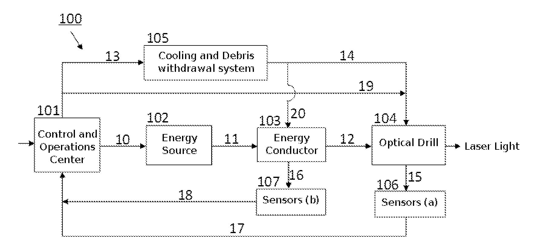
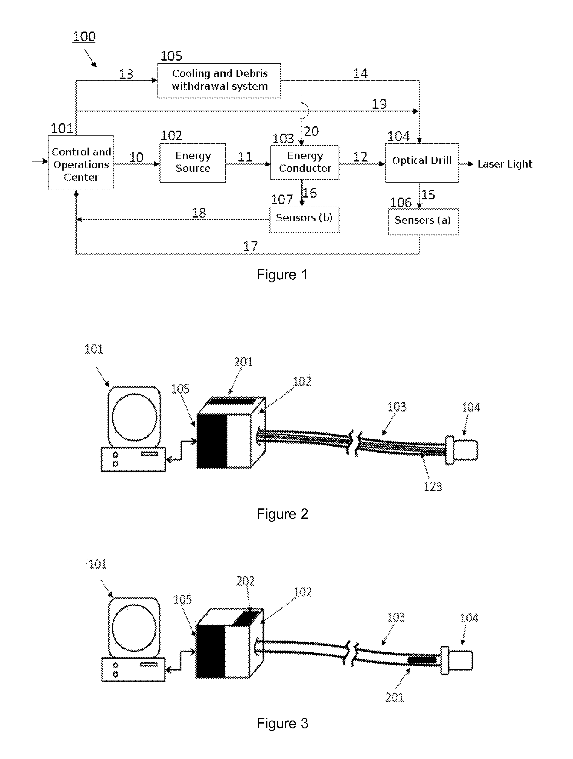
[0034]According to the concept of the invention a laser light system means both tunable lasers and lasers of different wavelengths and lasers based on different technologies such as, gas, solid state, dye, crystal, optical fiber, and the like and pulsed or continuous emission lasers. Those are positioned either near the supplying source or alternatively near the optical drill as will be detailed hereinbelow.

[0035]The drilling system makes use of high-intensity light generated by laser systems for drilling on-land and offshore wells as well as lateral orifices in walls of already existing wells—thus replacing perforating guns.

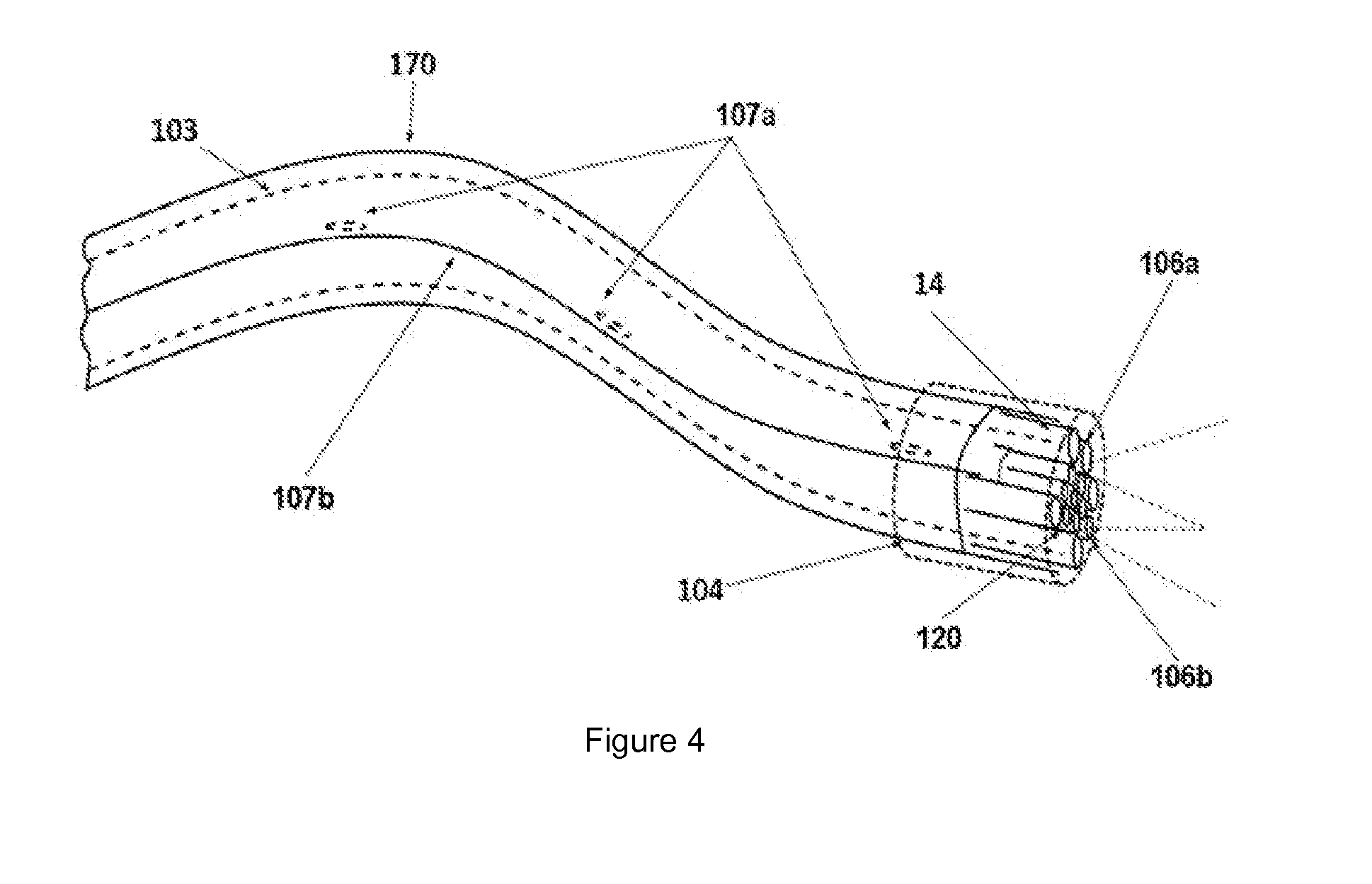
[0036]The high-intensity laser light is conveyed to the surface to be drilled with the aid of optical fibers. According to the distance that the light should travel until the surface to be drilled, the laser light wavelength and the optical density required for the drilling, the optical fiber can be vitreous or crystalline, mono- or multi mode, of varied refract...


PUM

PropertyMeasurementUnit
Wavelengthaaaaaaaaaa
Energyaaaaaaaaaa
Refractive indexaaaaaaaaaa

Abstract

A laser drilling system (100) for drilling rocks, soil and engineering materials with the aid of high-intensity laser light is described, which comprises an optical drill (104) for supplying laser light for the drilling of said materials provided with sensors (106); a control and operations center (101) comprising computer and supervising software with integrated logic; a cooling and debris withdrawal system (105) an energy source (102); an energy conductor (103) provided with sensors (107) and laser systems (201) for emitting high-intensity laser light and optical fibers (123) for conducting the so-generated laser light, so that the information collected by sensors (106), (107) supply said control and operations center (101) and said control and operations center (101) determines improved operation conditions of the optical drill (104) for the drilling of said solid materials or mixtures of solid and liquid materials relative to state-of-the-art drilling systems. The drilling method employing the system of the invention is also described.

Description

FIELD OF THE INVENTION[0001]The present invention relates to the field of laser drilling systems, more specifically, to a laser drilling system and method for drilling rocks, soil and engineering materials with the aid of high-intensity laser light. The drilling system of the invention comprises auxiliary systems or subsystems designed for cooling, withdrawal of debris, sensing and imaging, positioning and control and system management as a whole (laser(s), optical fiber(s) and optical, mechanical and electronic devices). These subsystems are integrated to the main optical system.BACKGROUND OF THE INVENTION[0002]The drilling of wells utilizing high-intensity laser light was proposed in the seventies as an alternative to the drilling with mechanical drills, as per the references cited below in the present specification.[0003]In this respect, U.S. Pat. No. 3,977,478 to Shuck states that laser drilling of subterranean earth formations is efficiently accomplished by directing a collimat...

Claims


Application Information

Patent Timeline
IPC IPC(8): B23K26/38
CPCB28D1/146H01S3/1305H01S3/0007E21B7/14
Inventor BRAGA, ARTHUR MARTINS BARBOSAMARTELLI, CICERO
Owner FACULDADES CATOLICAS MANTENEDORA DA PONTIFICIA UNIV CATOLICA DO RIO DE JANEIRO - PUC RIO
Why Eureka
Try Eureka