Camera module

a technology of camera module and camera body, which is applied in the field of camera module, can solve the problems of increased manufacturing cost, longer time for filling with potting material, and obstacle to size reduction, and achieve the effect of reducing the size of the camera module, facilitating assembly, and using safely

Inactive Publication Date: 2011-11-17
SMK CORP
View PDF9 Cites 49 Cited by
  • Summary
  • Abstract
  • Description
  • Claims
  • Application Information

AI Technical Summary

Benefits of technology

[0028]In the present invention, the vehicle-mounted camera module includes the optical system holder composed of the substrate supporting part in the form of a square box with a down-facing opening, and the cylindrical lens unit fixing part provided integrally with the substrate supporting part and formed at the center of the top of the substrate supporting part. The lens unit is supported in the lens unit fixing part, and the image capturing element holding substrate on which the image capturing element is mounted is fixed in the substrate supporting part. The substrate holder is coupled to an end portion of the substrate supporting part of the optical system holder, and the circuit component holding substrate is supported in the substrate holder. Accordingly, a circuit substrate can be easily added in order for the camera module to have more functions only by coupling the substrate holder to the optical system holder. This means that this camera module and a camera module that uses only a single image capturing element holding substrate can utilize parts common to each other, resulting in reduction in manufacturing cost.
[0036]Further, in the present invention, the elastic bushing has an outer circumference in the form of a tapered tube, the annular slot to tightly receive the inner peripheral edge of the cable through hole is formed in the outer circumference of the tip end portion of the elastic bushing, and the tapered tip end portion of the elastic bushing projects outside through the bottom surface of the outer case. Hence, the root of the cable at which the cable starts to be pulled is protected by the bushing, so that bending will not place local load on the root, thereby eliminating the risk of disconnection.

Problems solved by technology

In particular, if a shield fitting or a molded case is provided with a part for fixation of a corresponding substrate, a plurality of types of shield fittings or molded cases of different shapes should be prepared to respond to different functions of camera modules, resulting in increase in manufacturing cost.
Accordingly, the available area of substrate surfaces is made smaller by the area occupied by the connector, and this will be an obstacle to size reduction.
This results in longer time for filling with the potting material, while making it difficult to fill the space with the potting material sufficiently into details.
This results in poor workability, while damaging appearance if the cable is released from the temporary fixation too early, so that part of the cable coated with the potting material is pulled out.
If the cable is an FPC cable, for example, the bending strength of the cable is low at the root of the cable at which the cable starts to be pulled, resulting in a risk of a disconnection.

Method used


Image

  • Camera module
  • Camera module
  • Camera module

Examples


Embodiment Construction

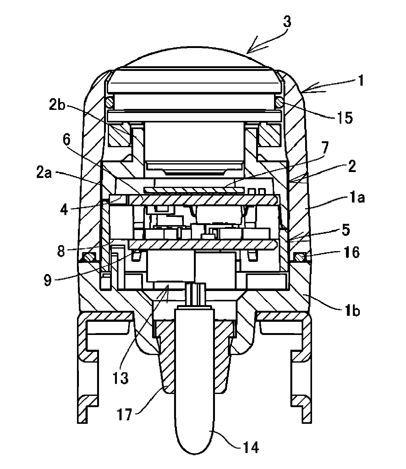
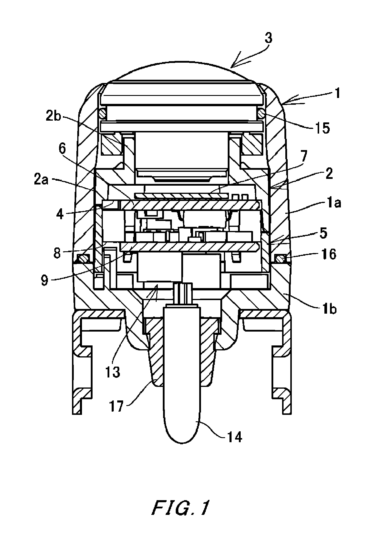
[0049]An embodiment of the present invention will be described with reference to examples shown in FIGS. 1 to 7.

[0050]In the drawings, reference numeral 1a indicates an outer case body, and reference numeral 1b indicates an outer case bottom cover that closes an opening at the bottom of the outer case body 1a. The outer case body 1a and the outer case bottom cover 1b are both formed by molding a synthetic resin, and together form an outer case 1.

[0051]The outer case 1 houses a molded optical system holder2 and a molded substrate holder 5 that are combined together.

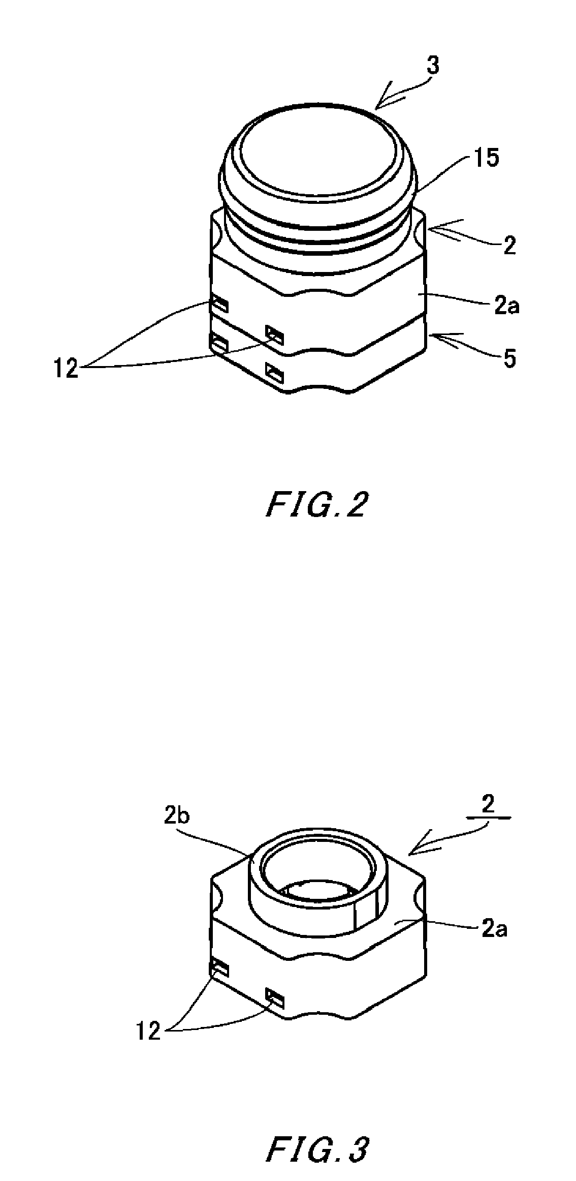
[0052]The optical system holder 2 includes a substrate supporting part 2a in the form of a square box with a down-facing opening, and a cylindrical lens unit fixing part 2b provided integrally with the substrate supporting part 2a and formed at the center of the top of the substrate supporting part 2a. One end of the lens unit 3 threadedly engages with the inside of the lens unit fixing part 2b.

[0053]Although not shown sp...


PUM


Abstract

Manufacture of molded cases of various types is not required even if the molded cases house different numbers of substrates, so that cost of manufacturing camera modules with various functions is reduced. A camera module includes an optical system holder composed of a substrate supporting part in the form of a square box with a down-facing opening, and a cylindrical lens unit fixing part provided integrally with the substrate supporting part and formed at the center of the top of the substrate supporting part. A lens unit is supported in the lens unit fixing part, and an image capturing element holding substrate on which an image capturing element is placed is fixed in the substrate supporting part. A substrate holder is coupled to an end portion of the substrate supporting part of the optical system holder, and a circuit component holding substrate is supported in the substrate holder.

Description

CROSS REFERENCE TO RELATED APPLICATION[0001]The contents of the following Japanese patent applications and International patent application are incorporated herein by reference:[0002]Japanese Patent Application NO. 2010-052786 filed on Mar. 10, 2010,[0003]Japanese Patent Application NO. 2010-054081 filed on Mar. 11, 2010,[0004]Japanese Patent Application NO. 2010-054790 filed on Mar. 11, 2010, and[0005]International Patent Application NO. PCT / JP2010 / 064020 filed on Aug. 19, 2010.BACKGROUND[0006]1. Technical Field[0007]The present invention relates to a camera module mainly used as a vehicle-mounted camera module.[0008]2. Related Art[0009]A compact camera module for capturing an image of the back of an automobile has widely been used. Such a camera module uses a molded case that is composed of upper and lower cases. The upper case has a lens barrel in which a lens unit is fixed. The upper case houses a substrate fixed in a predetermined position, and an image capturing element such a...

Claims


Application Information

Patent Timeline
Patent Type & Authority Applications(United States)
IPC IPC(8): H04N7/18
CPCG02B13/001G03B17/08H04N5/2257H04N5/2254H04N5/2253H04N23/52H04N23/57H04N23/55H04N23/54
Inventor MANO, NOBUYUKITUCHIYA, MASAKIKASHIMA, MASAYOSHI
Owner SMK CORP
Why Eureka
Try Eureka