Control circuit for image-capturing device

Inactive Publication Date: 2011-11-17
SEMICON COMPONENTS IND LLC
View PDF4 Cites 12 Cited by
  • Summary
  • Abstract
  • Description
  • Claims
  • Application Information

AI Technical Summary

Benefits of technology

[0012]According to the present invention, data processing can be effectively performed for ca

Problems solved by technology

Furthermore, the processing for the output from the gyro sensor includes an integration proc

Method used


Image

  • Control circuit for image-capturing device
  • Control circuit for image-capturing device
  • Control circuit for image-capturing device

Examples


Embodiment Construction

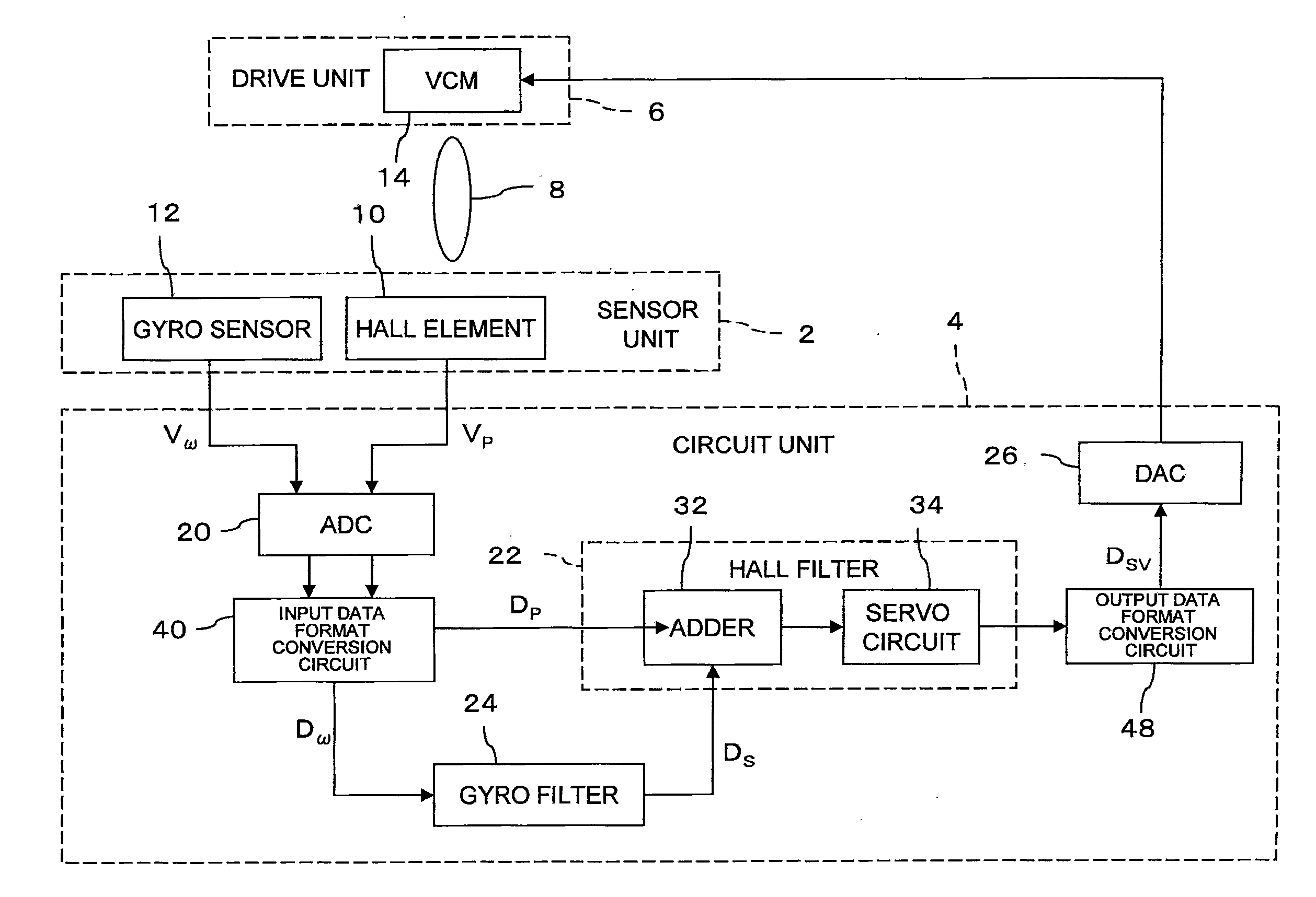
[0018]An embodiment of the present invention will be described hereinafter with reference to the attached drawings. The control device of the image-capturing device relating to the embodiment is used in a camera shake correction function.

[0019]FIG. 1 is a schematic block diagram of a camera shake correction system relating to the embodiment. The camera shake correction system has a sensor unit 2, a circuit unit 4, and a drive unit 6. The system adopts a method for camera shake correction by adjusting the position of a correction lens (lens 8), which is provided in an optical system forming an optical image on a light receiving surface of an image-capturing element (not shown) and used as a focus adjustment member.

[0020]The sensor unit 2 is composed of Hall elements 10 and gyro sensors 12. The Hall element 10 is a sensor for detecting the position of the lens 8 and generates and outputs a voltage signal VP to the circuit unit 4 in accordance with distance from the lens 8 on the basis...


PUM


Abstract

Performing data processing more effectively for camera shake correction is desirable. Movement of an image-capturing device is compensated on the basis of displacement velocity of the image-capturing device detected by a displacement velocity detector and position regarding a focus adjustment member of the image-capturing device detected by a position detector. An input data format converter converts the displacement velocity detected at the displacement velocity detector from fixed-point format to floating-point format and converts the detected position of the focus member to floating-point data. Furthermore, a gyro filter uses data processing in floating-point format to calculate displacement data for a required amount the image-capturing device is to be displaced and a Hall filter uses data processing in floating-point format to generate drive data for the focus adjustment member. Then, the drive data in floating-point format from the Hall filter is converted to drive data in fixed-point format.

Description

CROSS-REFERENCE TO RELATED APPLICATIONS[0001]The entire disclosure of Japanese Patent Application No. 2010-112878 filed on May 17, 2010, including specification, claims, drawings, and abstract, is incorporated herein by reference in its entirety.BACKGROUND[0002]1. Technical Field[0003]The present invention relates to a control circuit for an image-capturing device for calculating drive data for a focus adjustment member to compensate for movement of the image-capturing device on the basis of displacement velocity of the image-capturing device detected by a displacement velocity detector and position regarding the focus adjustment member of the image-capturing device detected by a position detector.[0004]2. Background Art[0005]Image-capturing devices, such as digital cameras or cameras mounted in cellular telephones, are increasingly equipped with a camera shake correction function to prevent a reduction in image quality due to camera shake. Various types of camera shake correction m...

Claims


Application Information

Patent Timeline
IPC IPC(8): H04N5/228G03B5/00
CPCG03B13/36G03B2205/0007H04N5/23287H04N5/23258G03B2217/005H04N23/6812H04N23/687
Inventor HIRAYAMA, HIDEKI
Owner SEMICON COMPONENTS IND LLC
Why Eureka
Try Eureka