Light guide member, laser light guide structure body, laser shining apparatus, and light source apparatus

a technology of laser shining apparatus and light guide member, which is applied in the direction of lighting and heating apparatus, semiconductor lasers, instruments, etc., can solve the problems of high production cost of prisms, difficult adjustment during assembly time, and high and achieve low production cost of light guide members. , the effect of simple structur

Inactive Publication Date: 2011-11-17
SHARP KK
View PDF2 Cites 15 Cited by
  • Summary
  • Abstract
  • Description
  • Claims
  • Application Information

AI Technical Summary

Benefits of technology

[0011]The present invention has been made in light of the above conventional problems, it is an object of the present invention to provide a light guide member that is producible at low cost, easy to adjust during an assembly time and efficiently guides laser light; a laser light guide structure body, a laser light shining apparatus and a light source apparatus that have the light guide member.
[0019]According to the present invention, the production cost of the light guide member is low, the positional adjustment between the light guide member and the semiconductor laser device is easy. Besides, a laser light guide structure body which has a simple structure is achieved. The light guide member efficiently guides laser light by reflection, especially a plurality of lines of laser light, from the incident surface to the output surface. In addition, the laser light guide structure body easily meets total-reflection conditions. By means of such light guide member, it is possible to provide a laser light shining apparatus or a light source apparatus that is small and inexpensive.

Problems solved by technology

In a case of the prism 100, the prism needs to be provided with an internal structure that has an uneven refractive index and is complicated, so that there is a problem that the production cost becomes high.
Besides, precise positioning between the light emitting portions of the plurality of semiconductor laser devices and the inlets of the plurality of waveguides at the prism incident surface is necessary, so that there is a problem that the adjustment during an assembly time becomes hard.
In a case of the prism 200 or the prism 300, the incident surface of the prism needs to be provided with a plurality of lens portions for collecting the laser light in a major-axis direction, so that there is a problem that the production cost of the prism becomes high.
Besides, precise positioning between the plurality of light emitting portions of the laser oscillator and the plurality of curved-surface portions of the incident surface of the prism is necessary, so that there is also a problem that the adjustment during an assembly time becomes hard.

Method used


Image

  • Light guide member, laser light guide structure body, laser shining apparatus, and light source apparatus
  • Light guide member, laser light guide structure body, laser shining apparatus, and light source apparatus
  • Light guide member, laser light guide structure body, laser shining apparatus, and light source apparatus

Examples


Embodiment Construction

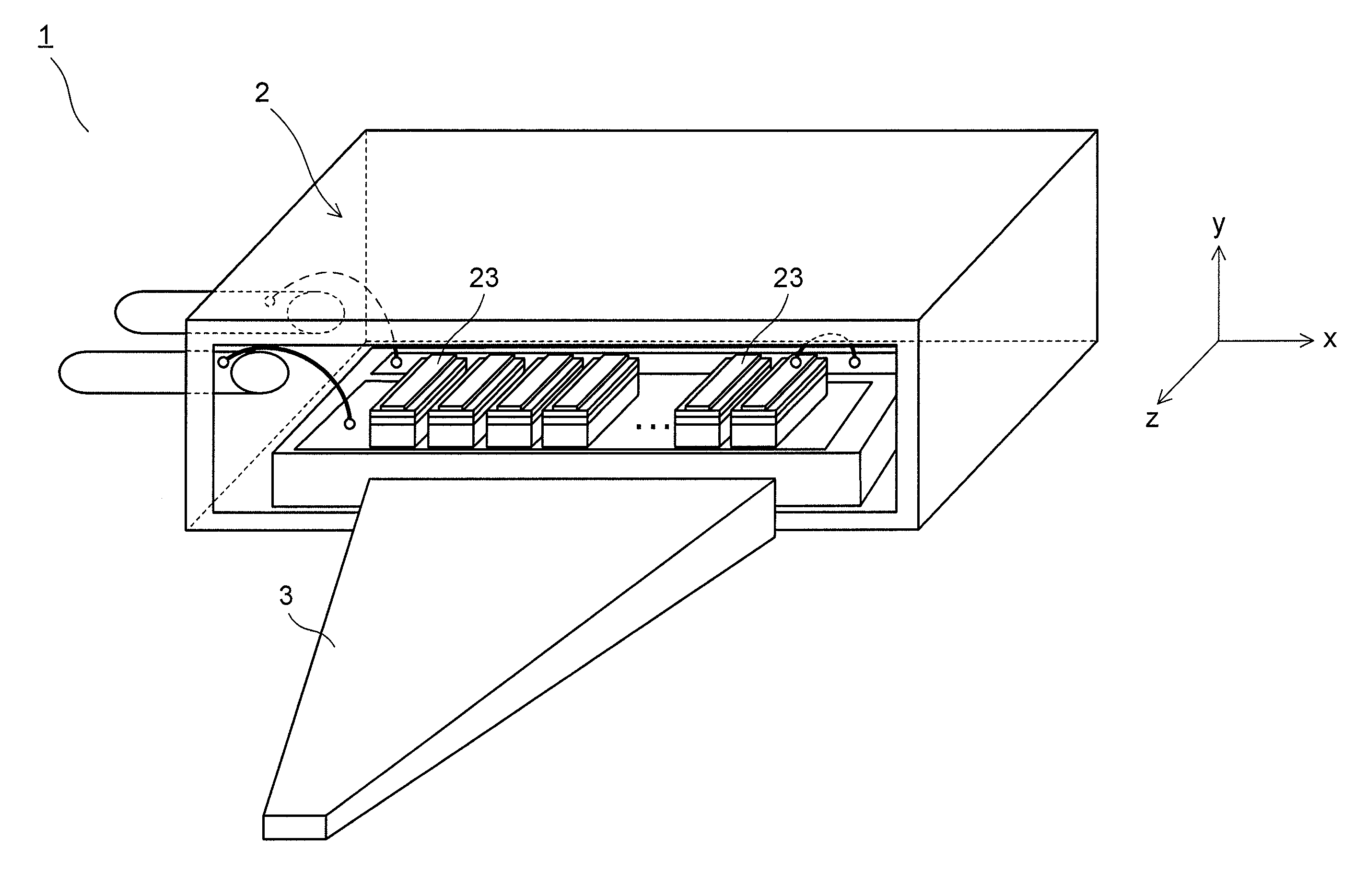
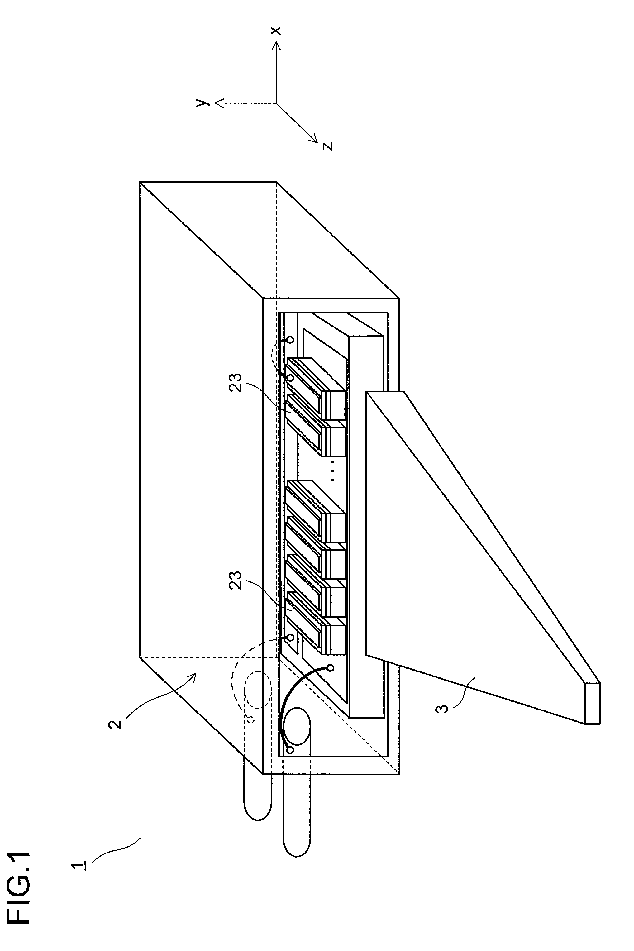
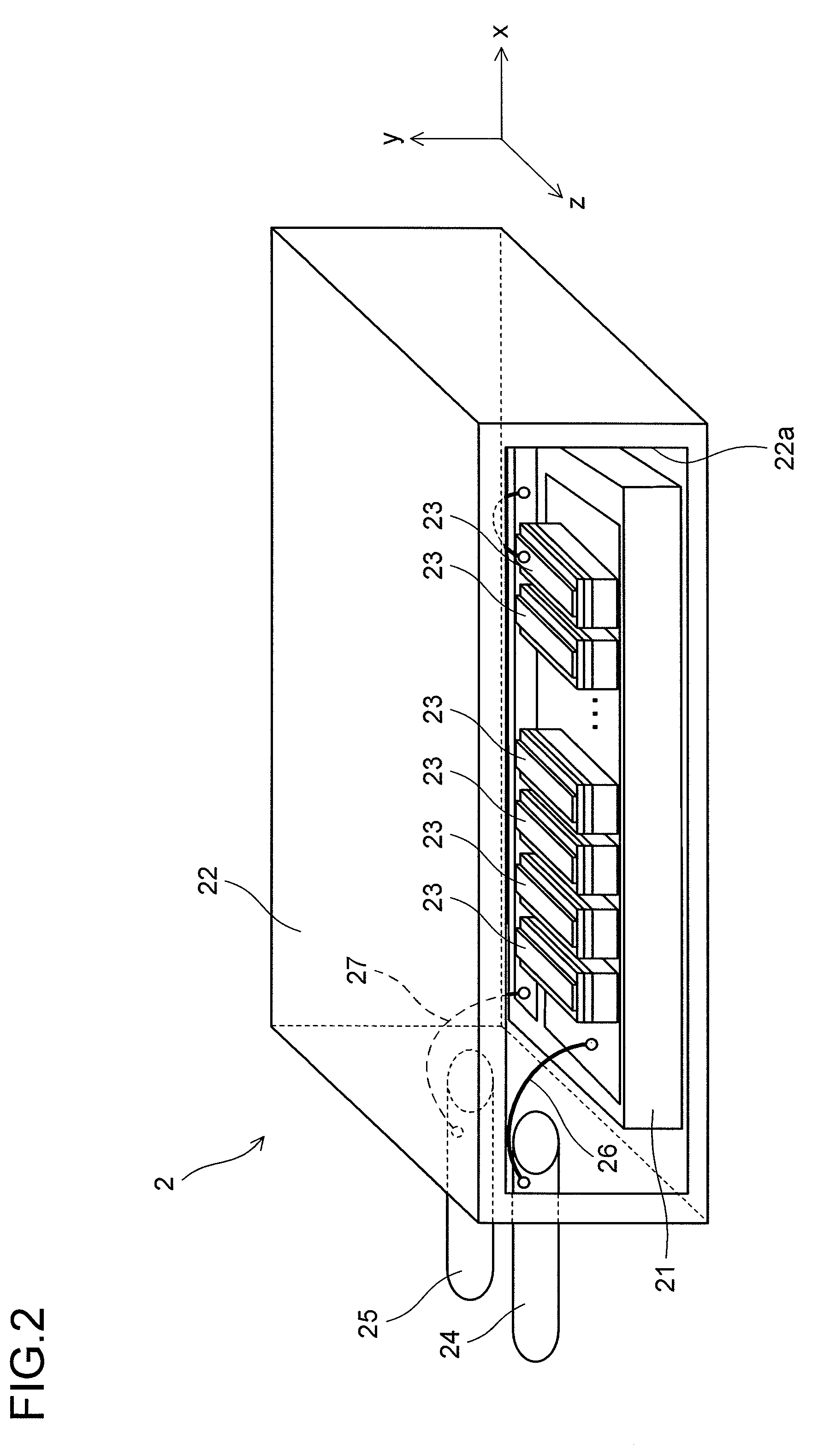
[0048]Hereinafter, embodiments of the present invention are described with reference to the drawings. In the following description, three-dimensional coordinate axes (x, y, and z axes) are used, of which the x axis represents a minor-axis direction of laser light, the y axis represents a major-axis direction of the laser light, and the z axis represents an optical-axis direction of the laser light.

[0049]FIG. 1 is a perspective view showing an embodiment of a laser light guide structure body that uses a light guide member according to the present invention. As shown in FIG. 1, a laser light guide structure body 1 according to the present embodiment includes: a laser array unit 2 that has a plurality of light emitting portions; and a light guide member 3 that receives via an incident surface a plurality of lines of laser light emitted from the laser array unit 2, guides the plurality of lines of received laser light in a predetermined direction and outputs them from an output surface....


PUM


Abstract

A light guide member 3 includes: an incident surface 3a that is a flat surface or a constant curved surface; an output surface 3b that is smaller than the incident surface 3a; and reflection surfaces 3c to 3f that are formed on a side surface between the incident surface 3a and the output surface 3b; wherein an inside of the light guide member 3 is homogeneous.

Description

[0001]This application is based on Japanese Patent Application No. 2010-110025 filed on May 12, 2010, the contents of which are hereby incorporated by reference.BACKGROUND[0002]1. Technical Field[0003]The present invention relates to: a light guide member: a laser light guide structure body, a laser light shining apparatus, and a light source apparatus that include the light guide member.[0004]2. Description of Related Art[0005]There are a plurality of conventional technologies that use a simple means to collect a plurality of lines of laser light that are emitted from a laser oscillator. These technologies use a laser array assembly as the laser oscillator in which semiconductor laser arrays, in which light emitting portions are arranged in a horizontal direction, are stacked in a vertical direction to dispose the individual light emitting portions into a two-dimensional matrix shape. And, as the light collection means, prisms, which are made of a transparent material such as quart...

Claims


Application Information

Patent Timeline
Patent Type & Authority Applications(United States)
IPC IPC(8): F21V13/02F21V9/16F21V8/00
CPCG02B6/2808G02B6/34G02B6/4296H01S3/094057H01S5/4025H01S5/02476H01S5/32341H01S5/4012H01S5/02216F21S41/16F21S41/176H01L2224/48091H01L2224/48463H01S5/0087H01S5/0225H01L2924/00014
Inventor TAKAHASHI, KOJI
Owner SHARP KK
Why Eureka
Try Eureka