
Load Balancing in Relay-Enhanced Access Networks

a load balancing and access network technology, applied in data switching networks, frequency-division multiplexes, instruments, etc., can solve problems such as system performance degradation, limit system performance, and limit system performan

Inactive Publication Date: 2011-11-17
NOKIA SOLUTIONS & NETWORKS OY +1
View PDF3 Cites 45 Cited by
  • Summary
  • Abstract
  • Description
  • Claims
  • Application Information

AI Technical Summary

Benefits of technology

The present invention and its embodiments are made to provide for a feasible solution for facilitating efficient load balancing in relay-enhanced access networks.
By way of exemplary embodiments of the present invention, there is provided a more flexible and robust architecture as well as mechanisms to solve capacity bottleneck problems, i.e. to facilitate efficient load sharing, in relay-enhanced access networks.
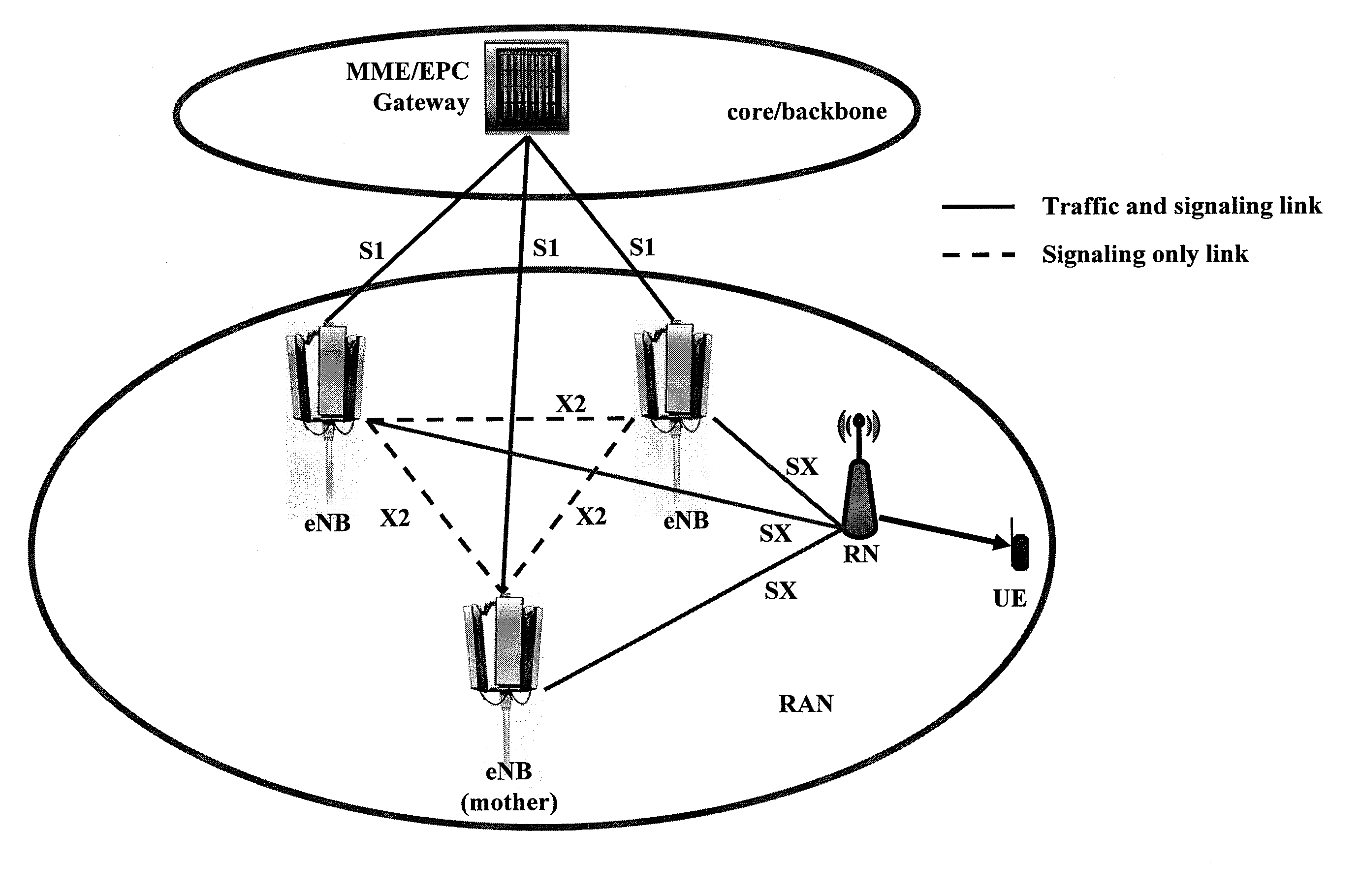
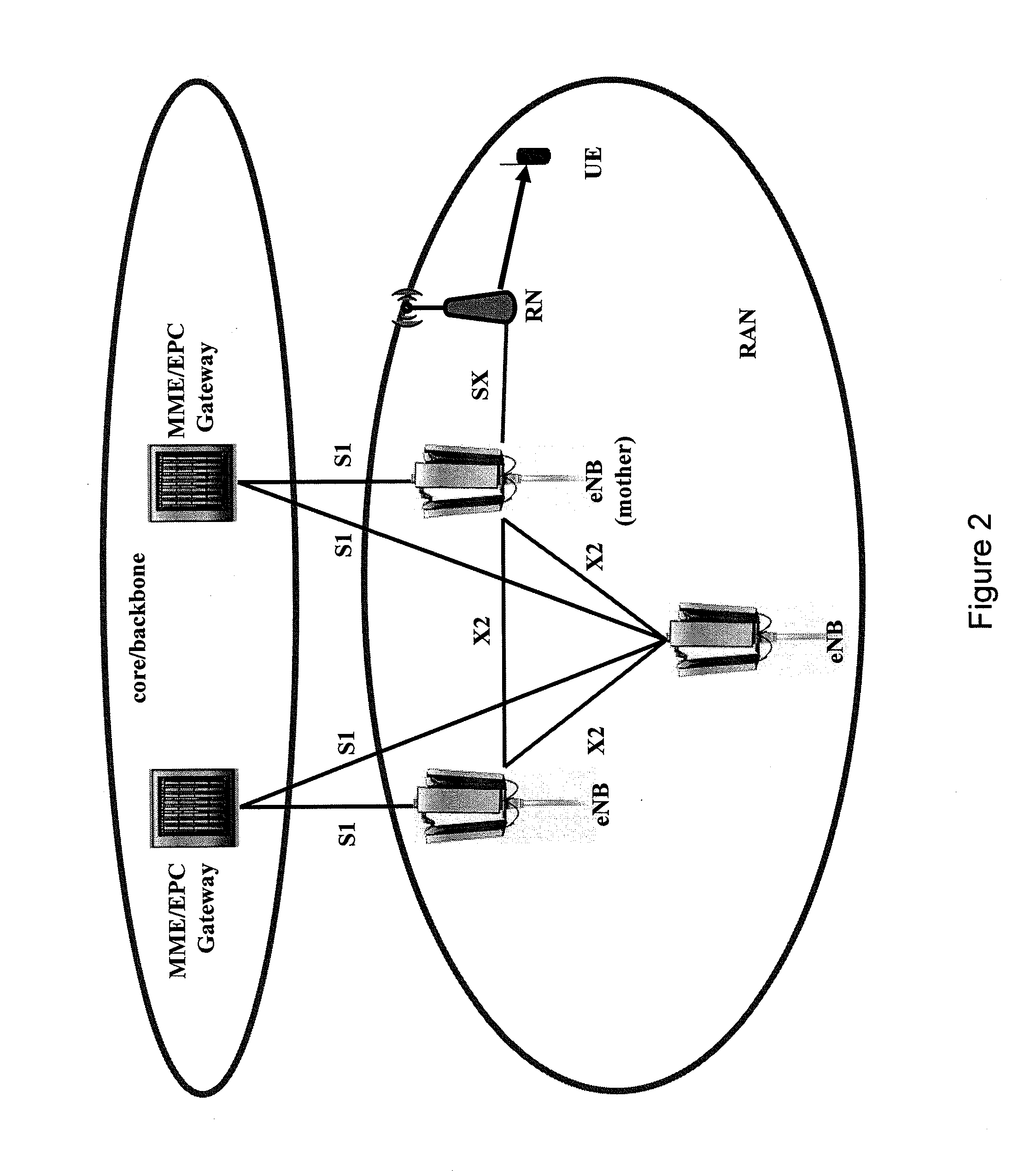
By way of exemplary embodiments of the present invention, there is provided a more flexible and robust architecture as well as mechanisms to resolve capacity bottlenecks due to the above-outlined one-to-one correspondence between a relay node and an access node. Accordingly, it is proposed that multiple connections between relay node and core network are established, so that data of relayed user equipments may be transported to and from the core network via multiple connections (i.e. multiple eNBs) instead of just one connection via the mother eNB. Stated in other words, it is proposed that links between access network and backbone network (i.e. S1 links in case of LTE) of more than one access node (i.e. eNB in case of LTE) are shared.
By way of exemplary embodiments of the present invention, there is provided a more flexible and robust architecture as well as mechanisms to dynamically decide the route of data on the basis of current load conditions in an access network, thus obviating any predetermined dedicated path between end nodes.
By way of exemplary embodiments of the present invention, the following effects may be achieved. Distributed S1 relaying may be supported for example in a relay-enhanced (LTE) access network. Such a distributed S1 relaying may be transparent to the user equipments in the system, and as such e.g. Release 8 UEs will benefit from it. To this end, there is provided a decision mechanism at an access device (i.e. eNB), a relay device (i.e. RN) and a backbone device (i.e. gateway or central network controller) as to where to route the data (i.e. on which path of S1 / SX or S1 / X2 / SX links), and mechanisms for the re-sequencing of data arriving via several S1 interfaces at the backbone device and, in one approach, data coming via several SX interfaces at the relay device. The support of a distributed / shared S1 interface may not only make the system more robust to problems related to transport network under-dimensioning, but it may also make the system more flexible by creating alternatives for load sharing and load switching.

Problems solved by technology

However, in this architecture, there exist problems regarding system performance due to potential capacity bottlenecks.
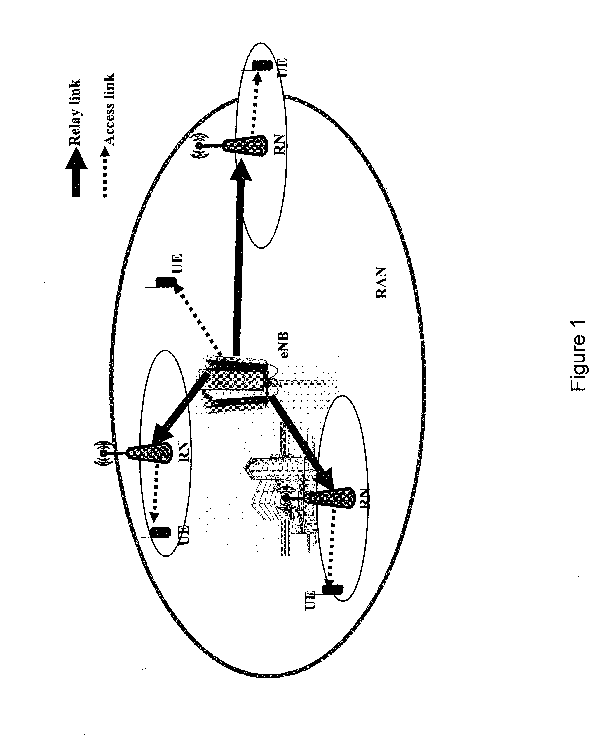
The fact that there is a one-to-one correspondence between a relay node RN and an access node eNB (i.e. though an eNB can be connected to multiple RNs, a RN is connected only to one eNB), might limit the system performance because the end-to-end performance of relayed UEs will be constrained by the capacity available on the backbone link between the mother eNB and the core network (i.e. the link that is accessible through the S1 interface).
For example, even if there are sufficient radio resources for the relay link, the performance of relayed UEs can degrade, if there is congestion in the backbone.
In practice, S1 links are expensive, and there is usually not enough capacity on S1 links to support the maximum cell capacity offered by the air interface provided by an access node eNB.
Apart from the backbone that can turn out to be a capacity bottleneck, there may be insufficient resources on the relay link between the relay node RN and the mother eNB.
Though handover to the lightly loaded cell may be an option for dealing with this load situation, a handover is not a totally flexible solution as back and forth handover of the relay and all its relayed UEs between eNBs can be an expensive procedure (e.g. in terms of capacity, overload, etc.).
However, after handover again, the same capacity bottlenecks as in the old cell (i.e. on the S1 interface and on the relay link) may prevail.
Thus, performing a handover for load sharing may generally not improve the overall system performance in relay-enhanced access networks.
Accordingly, there does not exist any feasible solution for facilitating efficient load balancing in relay-enhanced access networks.

Method used


Image

  • Load Balancing in Relay-Enhanced Access Networks
  • Load Balancing in Relay-Enhanced Access Networks
  • Load Balancing in Relay-Enhanced Access Networks

Examples


Embodiment Construction

The present invention and its embodiments are made to provide for a feasible solution for facilitating efficient load balancing in relay-enhanced access networks.

According to an exemplary first aspect of the present invention, there is provided a method being operable at a backbone device of a backbone network, comprising acquiring resource information of multiple access devices of an access network, said resource information indicating resource availability and resource assignment of said multiple access devices for establishing multiple connections between said backbone device and a relay device of said access network via said multiple access devices, setting multiple links between said backbone device and said multiple access devices, and managing resource allocation of said multiple links between said backbone device and said multiple access devices in accordance with said resource information.

According to further developments or modifications thereof, one or more of the followi...


PUM


Abstract

There are provided measures for load balancing in relay-enhanced access networks with a relay device and multiple access devices, said measures exemplarily including the setting of multiple links between a backbone device of a backbone network and said multiple access devices, and a management of resource allocation of said multiple links between said backbone device and said multiple access devices in accordance with resource information of said multiple access devices indicating resource availability and resource assignment of said multiple access devices for establishing multiple connections between said backbone device and said relay device via said multiple access devices.

Description

FIELD OF THE INVENTIONThe present invention generally relates to load balancing in relay-enhanced access networks. Specifically, the present invention relates to load balancing in relay-enhanced access networks comprising a relay device and multiple access devices.BACKGROUND OF THE INVENTIONIn the development of radio communication systems, such as mobile communication systems (like for example GSM (Global System for Mobile Communication), GPRS (General Packet Radio Service), UMTS (Universal Mobile Telecommunication System) or the like), efforts are made for an evolution of the radio access part thereof. In this regard, the evolution of radio access networks (like for example the GSM EDGE radio access network (GERAN) and the Universal Terrestrial Radio Access Network (UTRAN) or the like) is currently addressed in research and development as well as in standardization. Accordingly, such improved radio access networks are sometimes denoted as evolved radio access networks (like for ex...

Claims


Application Information

Patent Timeline
Patent Type & Authority Applications(United States)
IPC IPC(8): H04W28/08H04L45/125
CPCH04B7/2606H04L45/125H04L45/38H04L47/125H04W16/26H04W92/045H04W48/16H04W72/02H04W76/02H04W84/047H04W88/04H04W28/08H04W76/10H04W28/086
Inventor RAAF, BERNHARDREDANA, SIMONETEYEB, OUMERVAN PHAN, VINH
Owner NOKIA SOLUTIONS & NETWORKS OY
Learn More