
System and method for dynamic configuration of session layer retry logic based on signal quality

a dynamic configuration and signal transmission technology, applied in the field of system and method for dynamic configuration of signal transmission attempts, can solve the problems of rf signal strength, insufficient strength of radio frequency (rf) signal strength, and impede efficient and cost-effective wireless transaction authorization

Inactive Publication Date: 2011-11-17
APRIVA
View PDF7 Cites 21 Cited by
  • Summary
  • Abstract
  • Description
  • Claims
  • Application Information

AI Technical Summary

Benefits of technology

[0009]In general, the present invention overcomes the limitations and problems of the prior art by providing a system and method for facilitating transaction retry attempts based on network QoS. The present invention incor

Problems solved by technology

However, drawbacks remain that can hinder efficient and cost effective wireless transaction authorization.
For example, Radio Frequency (RF) signal strength is not available in sufficient strength in all locations at all times. In contrast, RF signal strength may be of sufficient strength but lack the clarity required for data transmission.
Signalnoise” may be introduced by any number of variables, thereby causing the signal to be unusable even when signal strength is optimal.
Signal noise has other causes such as buildings, electrical interference, or interference from competing signals.
Some terminals include more complex logic for establishing a wireless connection with a processing server.
However, signal strength is only one factor that will determine whether a transaction may be successfully executed by way of a wireless network.
As such, certain QoS issues remain despite advances in wireless technology.
While this strategy can be effective, it is not as suitable for packet delivery over wireless links that are susceptible connectivity instability.
However, prior art systems do not dynamically address specific reception variables that are unique to the time and environment from which a signal connection originates.
This can lead to excessive retry attempts within a relatively small amount of time, for example, resulting in excess power consumption and network usage costs.

Method used


Image

  • System and method for dynamic configuration of session layer retry logic based on signal quality
  • System and method for dynamic configuration of session layer retry logic based on signal quality
  • System and method for dynamic configuration of session layer retry logic based on signal quality

Examples


Embodiment Construction

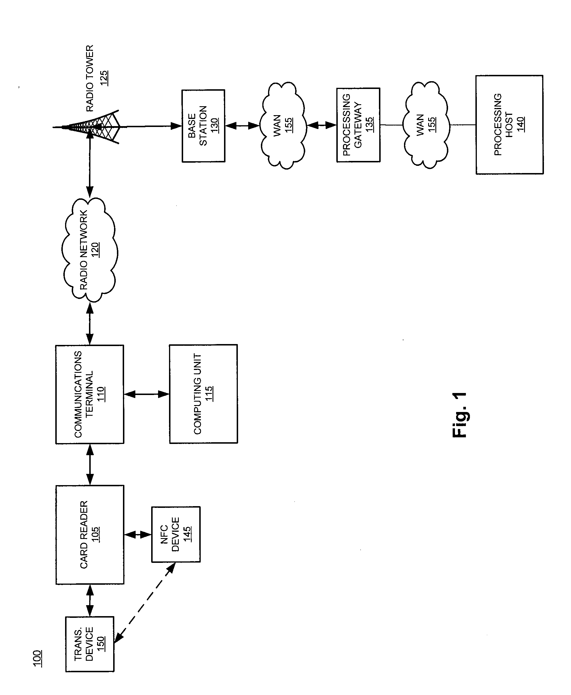
[0015]In general, the present invention dynamically configures retry logic within a communications terminal using a broadcast signal to communicate with a processing gateway. The subsequent description of the invention includes both the description of the Retry Object of the communications terminal, as well as the overall system architecture elements, such as a Secure Gateway and Session Initiation Protocol (SIP) Server as necessary, such that one of ordinary skill in the art will appreciate the present invention in full. However, it should be understood that such illustration of the communications terminal in relation to various servers, databases, and networks does not limit the scope of the invention.

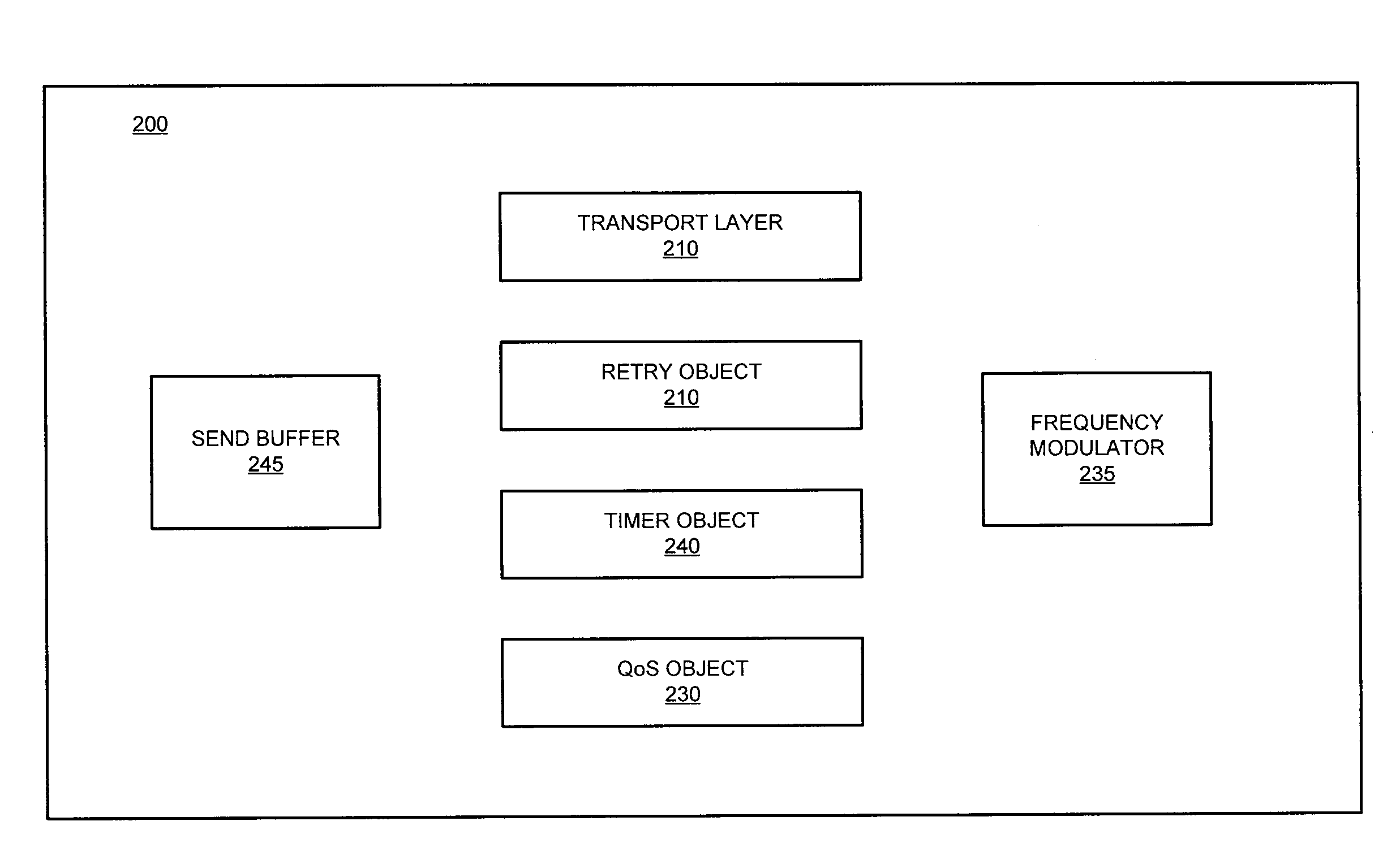
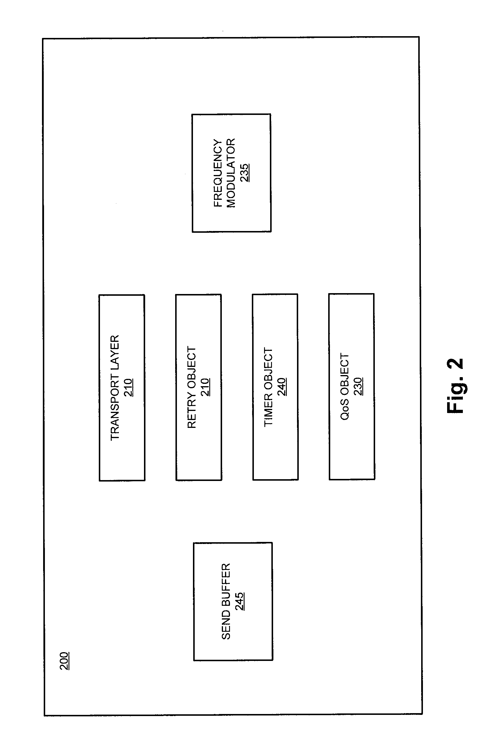
[0016]In an exemplary embodiment, the system interrogates a network to determine network signal quality of service (QoS) for any one or more accessible signals. A configurable Retry Object that resides within the Session Layer of the communications terminal determines whether a signa...


PUM


Abstract

The present invention involves the dynamic modification of network connection parameters based on signal conditions, and specifically, based on signal Quality of Service (QoS) measurements. Specifically, the disclosed systems and methods enable a remote communications terminal to best ensure a reliable wireless connection to a transaction-processing gateway in order to send and receive data packets relating to merchant transactions. The communications terminal is configurable, allowing a user to define threshold values that serve as triggering events for modifying and / or implementing a change to policies governing network connection attempts.

Description

FIELD OF THE INVENTION[0001]This invention relates generally to a method and system for a dynamic configuration of signal transmission attempts within a wireless networking environment. More specifically, the present invention may be incorporated within a cellular-based transaction terminal, which is configured to transmit a transaction request to a processor, and further configured to receive an authorization message from the processor.BACKGROUND[0002]Cellular telephone technology has had a dramatic impact on global commerce. Not only are business deals struck without regard to the physical locations of the parties involved, but funds are wirelessly transferred between the bank accounts of entities. Payment transactions that previously required access to a telephone line or other physical network connection now require little more than a mobile telephone or an Internet enabled wireless device.[0003]With increased cellular network coverage and faster network speeds, remote card-base...

Claims


Application Information

Patent Timeline
IPC IPC(8): H04J3/16
CPCH04L43/16H04L41/0816
Inventor KLINGEN, MIKE
Owner APRIVA
Learn More