Imaging apparatus comprising a ring-shaped gantry

a ring-shaped gantry and gantry technology, applied in the direction of electrical apparatus, x-ray apparatus, medical science, etc., can solve the problems of insufficient information acquisition, large space occupation, unsatisfactory tissue resolution, etc., and achieve the effect of arbitrary positioning of the patient positioning tabl

Inactive Publication Date: 2011-11-17
SIEMENS HEALTHCARE GMBH
View PDF3 Cites 18 Cited by
  • Summary
  • Abstract
  • Description
  • Claims
  • Application Information

AI Technical Summary

Benefits of technology

[0009]According to the invention the openable gantry is arranged on an articulated-arm robot secured to the floor, wall or ceiling, i.e. it is guided from below, from the side or from above. A transport cart that is movable across the floor or a similar contrivance is no longer provided according to the invention, thereby consequently considerably improving the accessibility of the gantry both with regard to the positioning of any equipment and for people as well as with regard to the possibility of easily positioning the patient.
[0010]The gantry is also characterized by the use of two radiation sources which are disposed offset by a defined angle from each other in or on the rotor arrangement. By means of said two radiation sources in conjunction with the associated detectors it is possible to record images at twice as high a heart rate or, as the case may be, to record a complete cardiac cycle in full even at the normal heart rate. Toward that end the two radiation sources are operated in parallel, the detectors continuously providing parallel images, though from different projection directions. As a result of this it is no longer absolutely necessary to administer any drugs to slow the heart rate on the one hand, while on the other hand high-quality images of a moving organ can be recorded even at somewhat lower rotational speeds.
[0011]In order to enable adequate freedom of movement and as a result thereof positioning freedom of the gantry it is already sufficient if the articulated-arm robot has at least four degrees of freedom of movement, with preferably five or in particular six degrees of freedom being provided. A further improvement in the freedom of movement or, as the case may be, positioning capability is given if the articulated-arm robot is mounted on the floor, wall or ceiling so as to be movable along at least one, preferably two horizontal or vertical axes standing perpendicularly relative to one another. By this means the entire arrangement consisting of robot and gantry can additionally be varied in terms of its space coordinates, thus further increasing the positioning freedom. The movement of the robot, whether it be its arms around the corresponding revolute joints themselves, whether it be the entire robot along the linear rail guides on the floor, wall or ceiling, is preferably effected by means of suitable motors which are arranged at the corresponding movement interfaces or engage there. To control the movement a suitable control device is provided via which all of the motors are controlled, for example using a joystick or a similar control element.
[0017]Furthermore a patient positioning table can be provided which can be moved translationally and / or rotationally in space. It can be adjusted manually or in a motor-driven manner in terms of its height, length and transverse direction, and can be fixed to the floor, wall or ceiling by way of a suitable supporting structure. An optional inclination in the x-, y- and / or z-direction is also possible, while the patient positioning table can also optionally rotate about a central point; a circular or elliptical rotational movement about a fixed point is also conceivable. In particular the use of an articulated-arm robot having at least four, preferably six, degrees of freedom is suitable for moving the patient positioning table, said articulated-arm robot, in particular if having six degrees of freedom, enabling translational and rotational movements in or about any spatial direction axis and consequently allowing an arbitrary positioning of the patient positioning table in space.

Problems solved by technology

However, X-ray machines of this kind generally provide only 2D images and sometimes the soft-tissue resolution is unsatisfactory or the image quality is not such that sufficient information can be acquired in particular in the case of complex interventions.
However, a disadvantage of the known mobile gantry is to be seen in the fact that e.g. the mobile cart on which the gantry is arranged takes up a considerable amount of space which is then no longer available for positioning other equipment required for a treatment or in which it is also not possible for persons involved in the treatment to remain.
This is disadvantageous for the patient on the one hand, and on the other hand optimal image acquisition is not always assured, especially at somewhat slower rotational speeds.

Method used


Image

  • Imaging apparatus comprising a ring-shaped gantry
  • Imaging apparatus comprising a ring-shaped gantry
  • Imaging apparatus comprising a ring-shaped gantry

Examples


Embodiment Construction

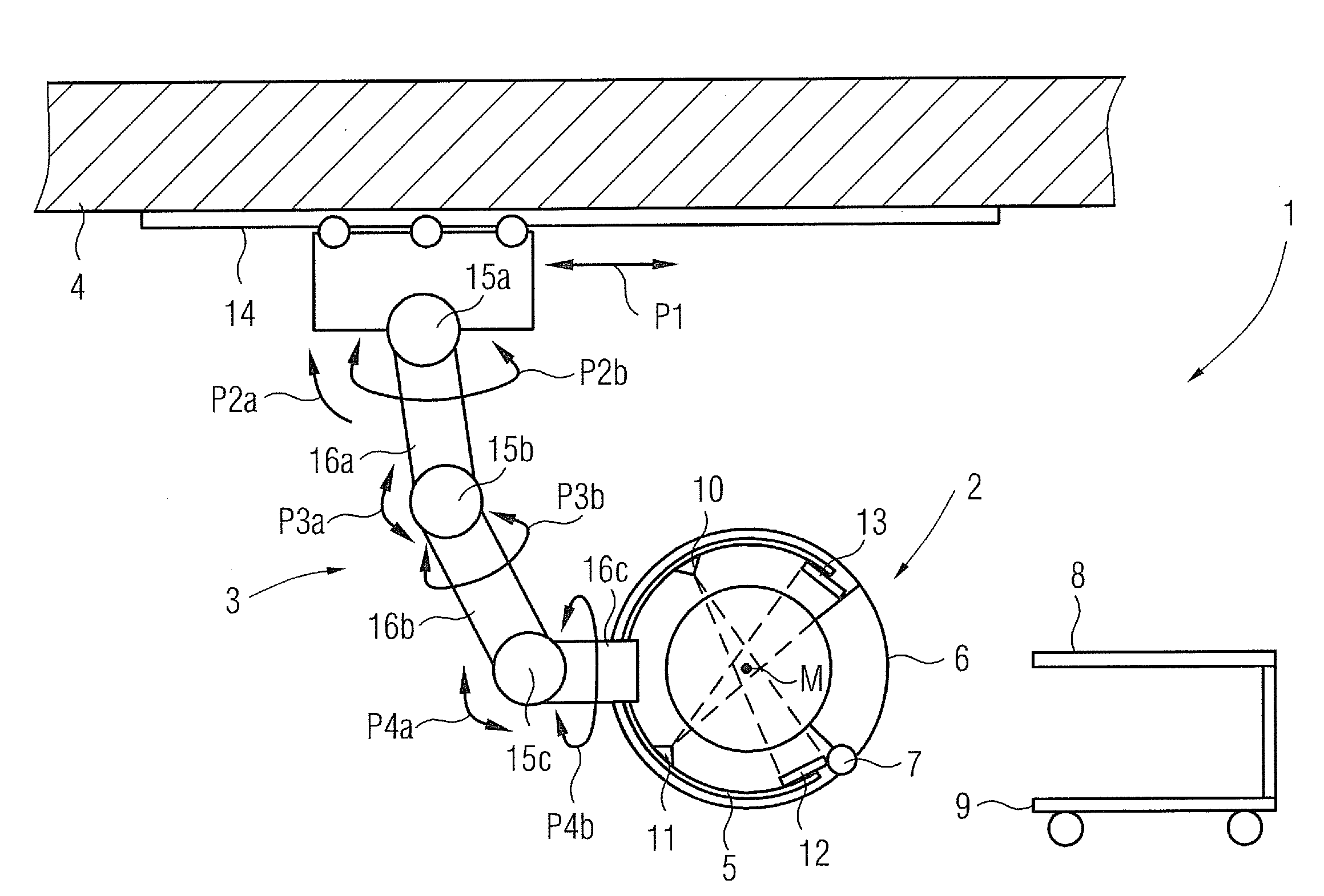
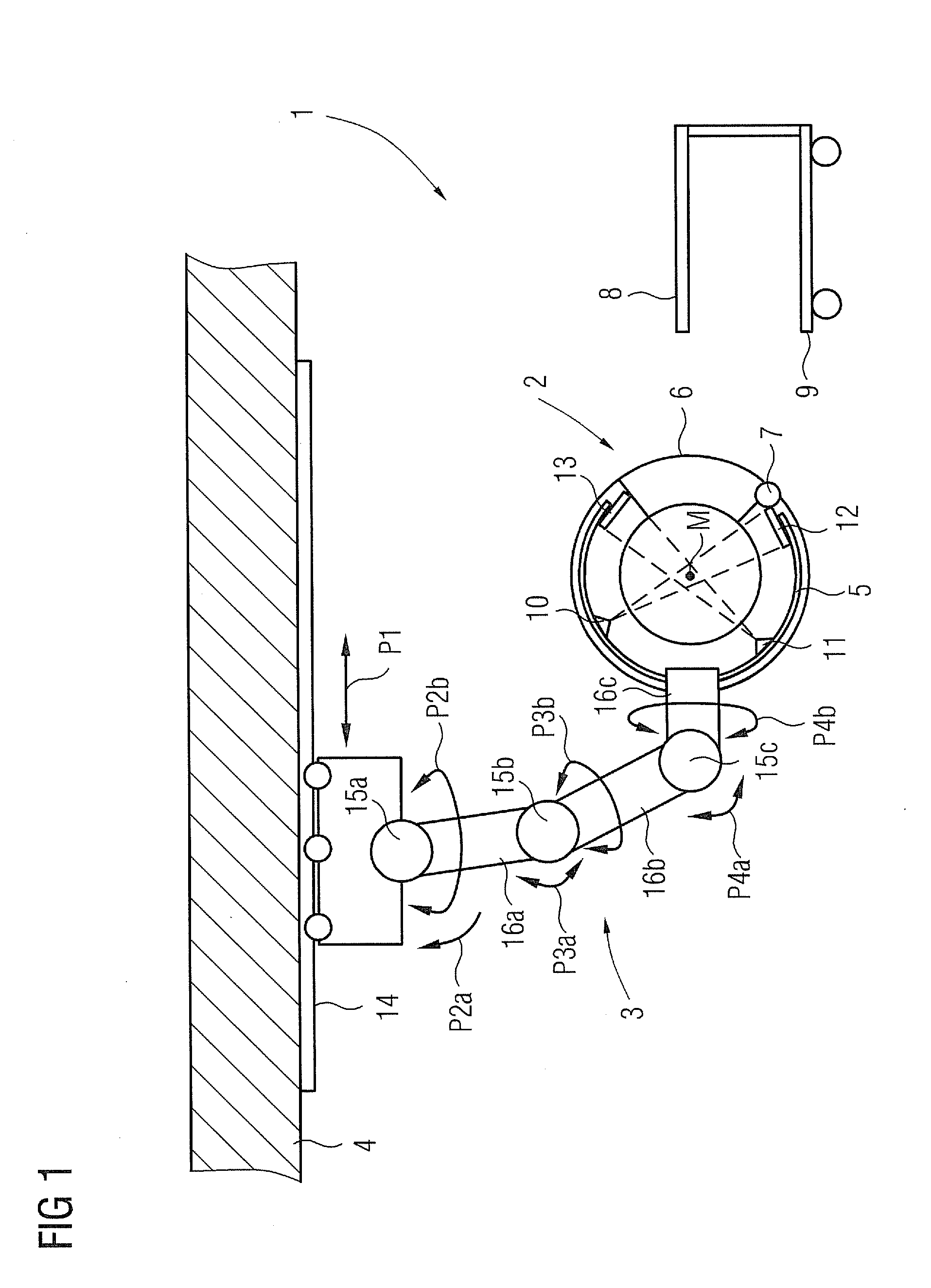
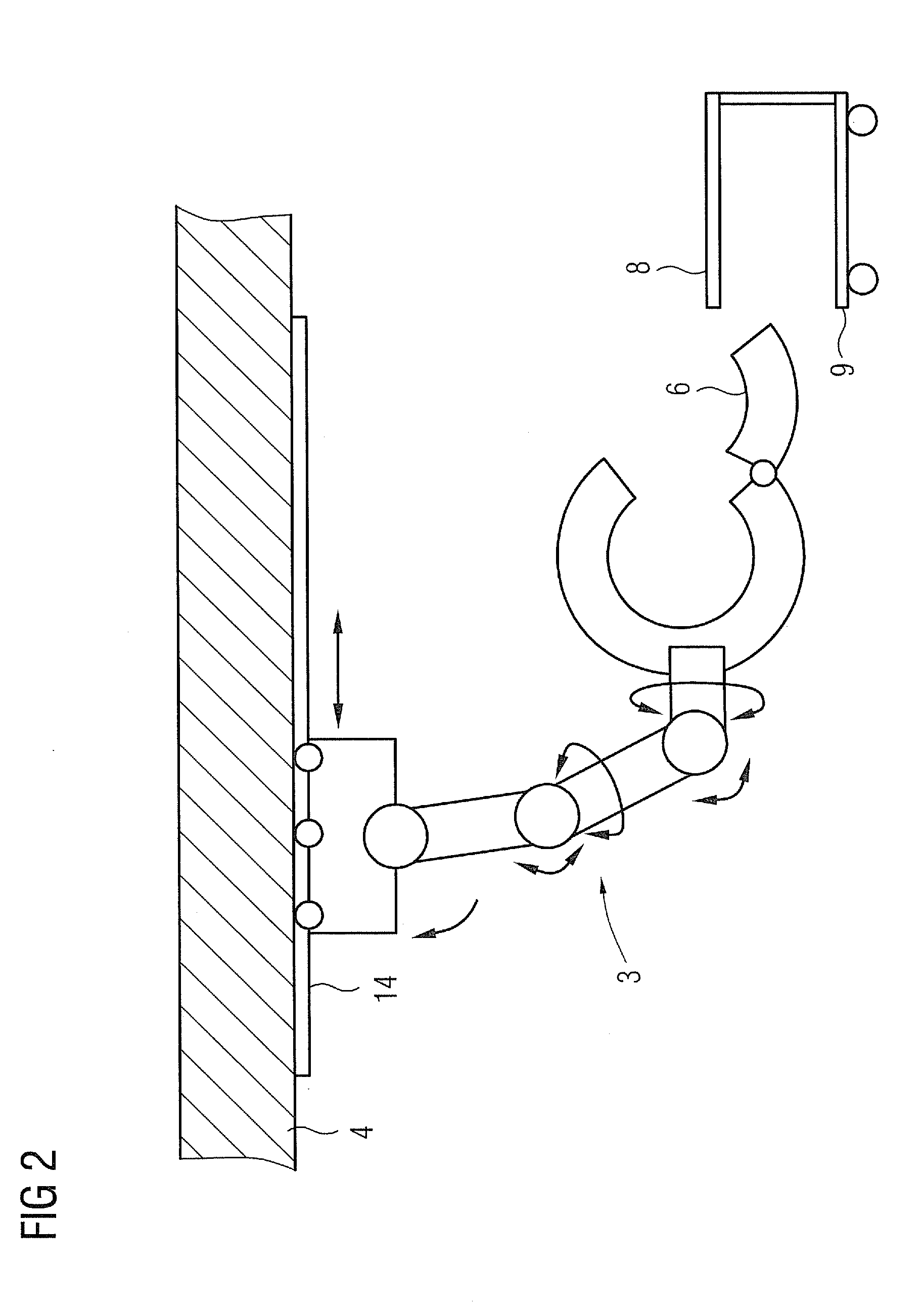
[0023]FIG. 1 shows in the form of a schematic diagram an imaging apparatus 1 according to the invention, comprising a gantry 2 which is arranged on a ceiling 4 so as to be movable by way of an articulated-arm robot 3. The gantry 2 comprises a rotor arrangement 5 which, driven by way of a motor, rotates about the center point M on runner rails (not shown in further detail) located inside the gantry 2. The rotor arrangement 5 extends through approx. 270°. This enables it to be brought into a park position in which a segment 6 of the gantry which is pivotably mounted by way of a hinge 7 can be swung open (see FIG. 2) so that the inside of the gantry 2 is accessible. It is now possible to position a patient (not shown in further detail) inside the gantry 2 by means of a patient positioning table 8 on which the patient is located and which in the example shown can be moved in space by way of a cart 9. Appropriate locking means (not shown in further detail) are of course provided for the ...


PUM


Abstract

An imaging apparatus comprising a ring-shaped gantry is provided. The gantry has a rotor arrangement rotating therein and a radiation source as well as at least one radiation detector. The gantry has at least one gantry segment which can be detached from the ring shape to allow the gantry to be opened laterally. The gantry is arranged on a supporting structure so as to be movable in space. The supporting structure is a floor, wall or ceiling mounted articulated-arm robot having at least four, preferably six, degrees of freedom of movement. The gantry has at least two radiation sources disposed offset by an angle on the rotor arrangement and associated with each of which is at least one radiation detector.

Description

CROSS REFERENCE TO RELATED APPLICATIONS[0001]This application claims priority of German application No. 10 2010 020 603.2 filed May 14, 2010, which is incorporated by reference herein in its entirety.FIELD OF THE INVENTION[0002]The invention relates to an imaging apparatus comprising a ring-shaped gantry having a rotor arrangement rotating therein and having an image acquisition means comprising a radiation source as well as at least one radiation detector, wherein the gantry having at least one gantry segment which can be detached from the ring shape to allow the gantry to be opened laterally is arranged on a supporting structure so as to be movable in space.BACKGROUND OF THE INVENTION[0003]Minimally invasive interventions and minimally surgical interventional procedures on patients are increasingly replacing traditional surgical operations. A factor of crucial importance in this regard is good anatomical and functional medical imaging, in particular of soft tissue, in the case of ...

Claims


Application Information

Patent Timeline
Patent Type & Authority Applications(United States)
IPC IPC(8): H05G1/02B82Y99/00
CPCA61B6/4411A61B6/4464A61B6/4458A61B6/4435A61B6/4441
Inventor MASCHKE, MICHAEL
Owner SIEMENS HEALTHCARE GMBH
Why Eureka
Try Eureka