Eureka AIR delivers breakthrough ideas for toughest innovation challenges, trusted by R&D personnel around the world.

System and methods for removing a loose tooth

Inactive Publication Date: 2011-11-17
CRANE COLTON
View PDF7 Cites 5 Cited by
  • Summary
  • Abstract
  • Description
  • Claims
  • Application Information

AI Technical Summary

Benefits of technology

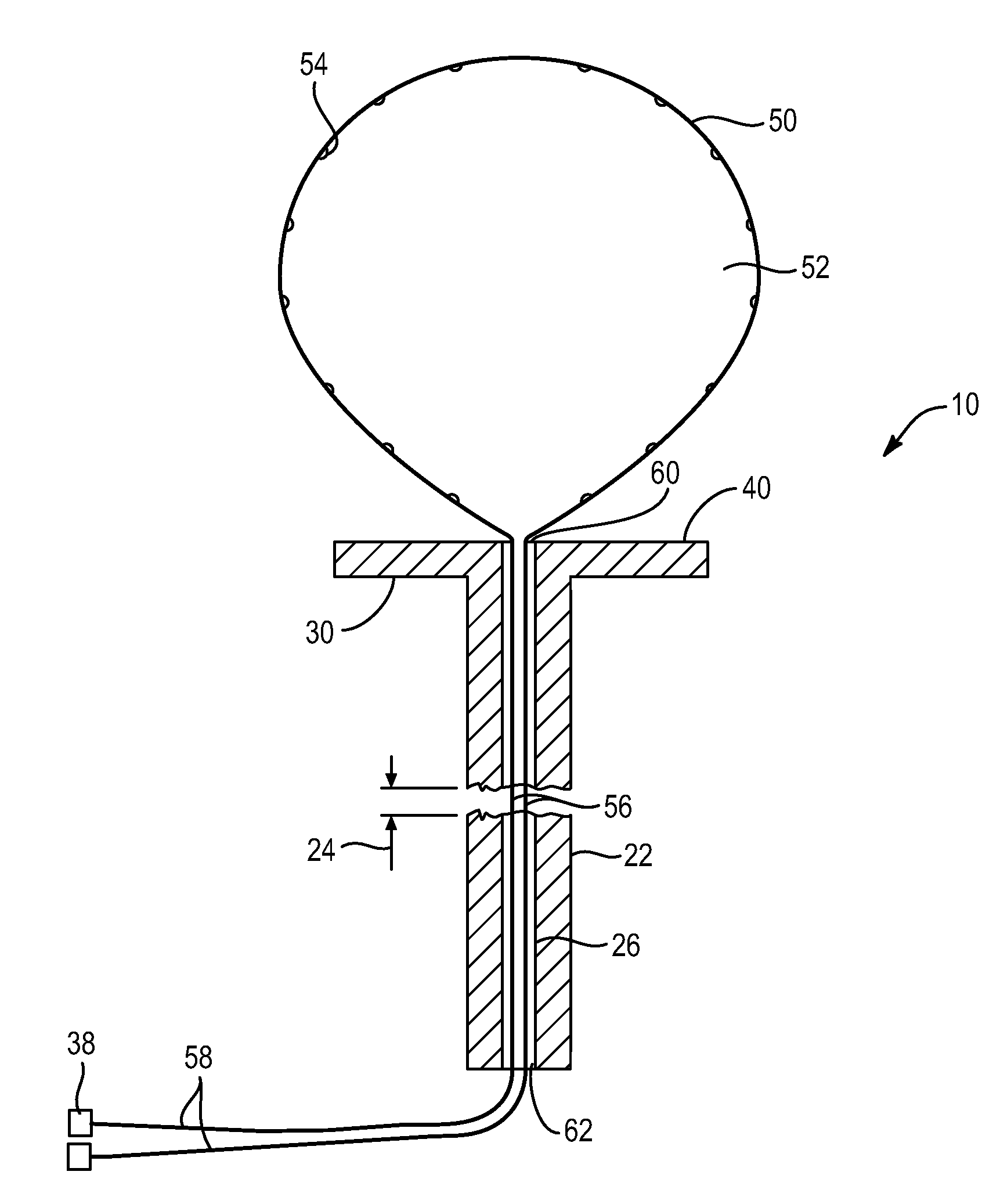
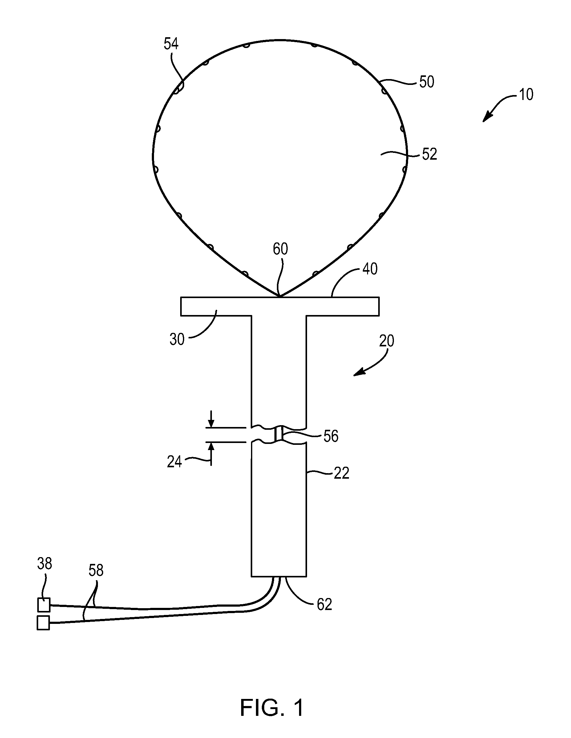
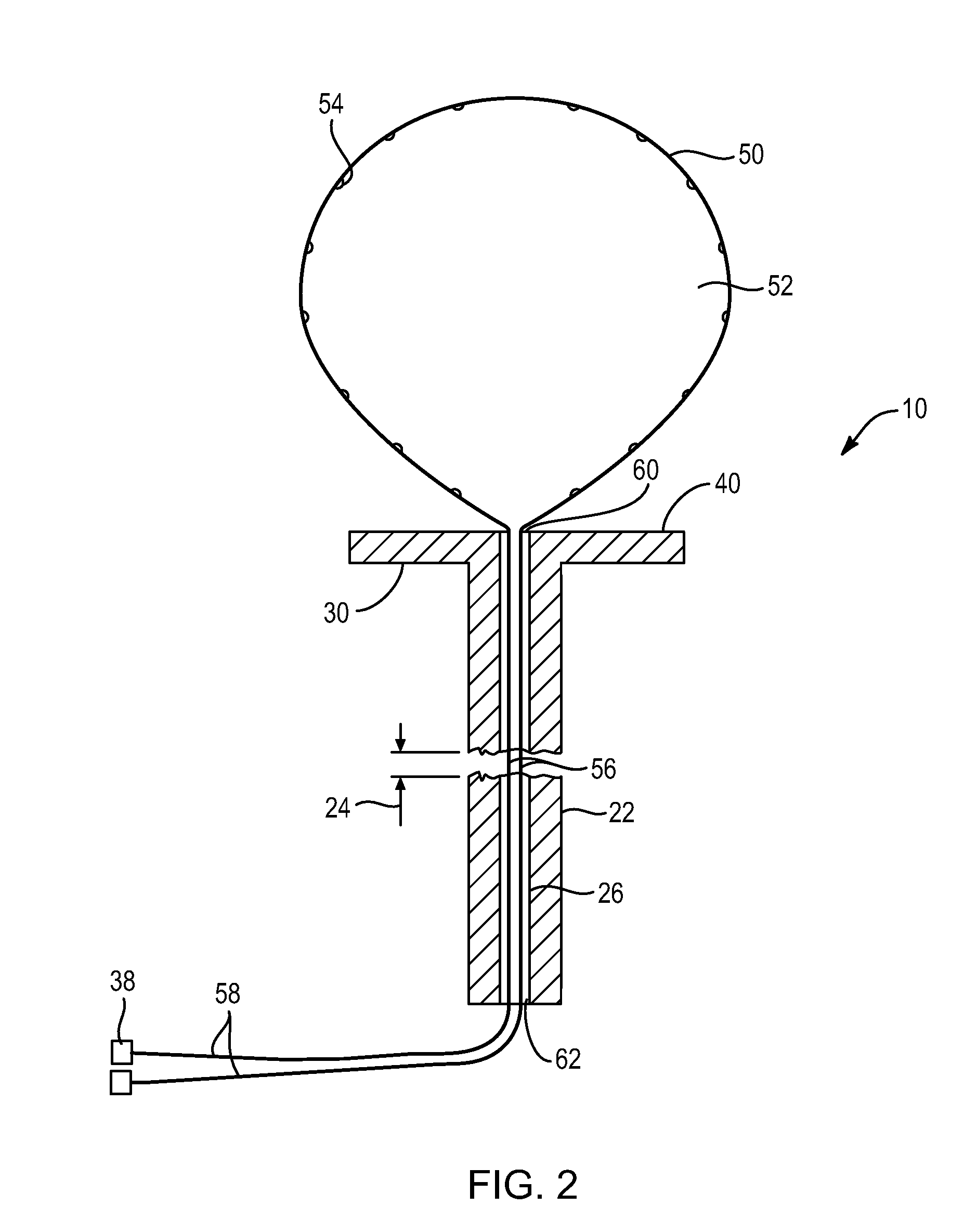
In some implementations, the retention strap forms a loop at the second end of the tubular handle. The retention strap is configured such that the loop is fitted about the loose tooth. A free end of the retention strap extends through the tubular handle exiting an opening located at the first end of the handle. A user adjusts the size and tension of the retention strap by withdrawing the free end from the first end of the handle. Thus, the loop acts as a snare or noose whereby the user is able to secure the tooth to the base structure by reducing the diameter of the loop around the outer diameter of the tooth.
In some implementations an outer surface of the tubular handle includes a texture or coating to increase the friction between the tubular handle and the user's grip. In other implementations, the outer surface of the tubular handle includes an ergonomic feature to enhance the user's ability to grip the tooth removal device. Further, in some embodiments the base structure of the device is extended laterally so as to overlap teeth adjacent to the loose tooth.

Problems solved by technology

It is well known that when children are losing their baby teeth, the shedding of each tooth is more than likely to involve several days of discomfort, peevishness, and difficulty of eating on the part of the child.
During this period, the tooth is so loose that each time anything touches the tooth, it tilts about and hurts the adjacent gums.
Attempts of parents to dislodge the tooth with the fingers during this period are usually unsuccessful, as the sizes and locations of the teeth usually make it very difficult to grasp the tooth with the fingers for a straight or slightly twisting pull.
However, this procedure is rarely successful, as the shape of the baby teeth is such that knotted threads have the habit of sliding off the tooth.
Further, few people know how to tie knots sufficiently tight to grip the tooth without pinching the tender gums adjacent to the tooth.
Additionally, while working with the loose tooth there is a propensity for the string to become bloody and covered with saliva thereby causing the string to become slippery and difficult to handle.
Thus, while methods exist to assist in removing loose baby teeth, challenges still exist.

Method used


Image

  • System and methods for removing a loose tooth
  • System and methods for removing a loose tooth
  • System and methods for removing a loose tooth

Examples


Embodiment Construction

The presently preferred embodiments of the present invention will be best understood by reference to the drawings, wherein like reference numbers indicate identical or functionally similar elements. It will be readily understood that the components of the present invention, as generally described and illustrated in the figures herein, could be arranged and designed in a wide variety of different configurations. Thus, the following more detailed description, as represented in the figures, is not intended to limit the scope of the invention as claimed, but is merely representative of presently preferred embodiments of the invention.

Referring now to FIG. 1, a loose tooth removal device 10 is shown. In general, a loose tooth removal device 10 in accordance with the present invention comprises a tubular handle 20 having a gripping surface 22 whereby a user grasps the device 10. In some embodiments, handle 20 comprises a rigid or semi-rigid polymer material, such as nylon, phenolic, epoxy...


PUM

PropertyMeasurementUnit
Sizeaaaaaaaaaa
Surfaceaaaaaaaaaa

Abstract

A device for removing a loose tooth, the device including a handle, a base structure, and a retention strap, wherein the retention strap is secured about an outer surface of the loose tooth such that the base structure forms an interface with the tooth. The device further including features for increasing friction between the base structure and the tooth to prevent slippage while removing the tooth with the device.

Description

BACKGROUND OF THE INVENTIONThe present invention relates to systems and methods for removing a loose tooth. In particular, the present invention relates to a device configured to secure a user's grip on a loose tooth thereby assisting the user in removing the tooth from the oral cavity.It is well known that when children are losing their baby teeth, the shedding of each tooth is more than likely to involve several days of discomfort, peevishness, and difficulty of eating on the part of the child. During this period, the tooth is so loose that each time anything touches the tooth, it tilts about and hurts the adjacent gums.Attempts of parents to dislodge the tooth with the fingers during this period are usually unsuccessful, as the sizes and locations of the teeth usually make it very difficult to grasp the tooth with the fingers for a straight or slightly twisting pull. Further, as the parents are afraid of hurting the child, they refrain from the painful process of forcing the toot...

Claims


Application Information

Patent Timeline
IPC IPC(8): A61C3/14B23P17/04
CPCY10T29/49826A61C3/14
Inventor CRANE, COLTON
Owner CRANE COLTON
Why Eureka
Eureka Blog
Learn More