Management apparatus, system including the management apparatus and multiple devices, and method of controlling the apparatus and the system

Inactive Publication Date: 2011-11-17
CANON KK
View PDF3 Cites 20 Cited by
  • Summary
  • Abstract
  • Description
  • Claims
  • Application Information

AI Technical Summary

Benefits of technology

[0008]An aspect of the present invention is to eliminate th

Problems solved by technology

However, with this conventional technology, a time period for performing control based on the upper limit value is not set.
Accordingly, after the power consumption reaches the upper l

Method used


Image

  • Management apparatus, system including the management apparatus and multiple devices, and method of controlling the apparatus and the system
  • Management apparatus, system including the management apparatus and multiple devices, and method of controlling the apparatus and the system
  • Management apparatus, system including the management apparatus and multiple devices, and method of controlling the apparatus and the system

Examples


Example

[0030]An embodiment of the present invention will now be described hereinafter in detail, with reference to the accompanying drawings. It is to be understood that the following embodiment is not intended to limit the claims of the present invention, and that not all of the combinations of the aspects that are described according to the following embodiment are necessarily required with respect to the means to solve the problems according to the present invention.

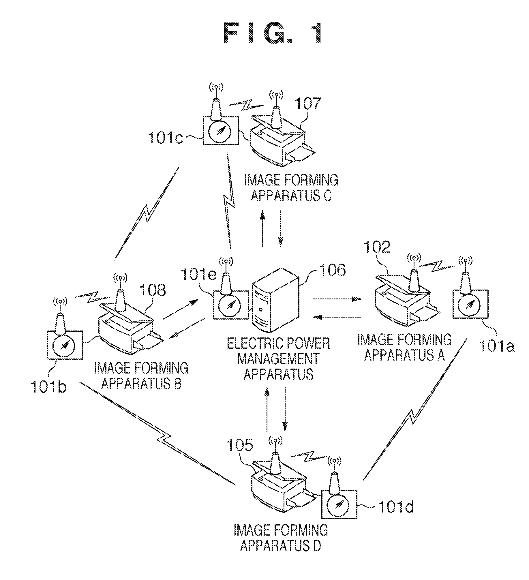
[0031]FIG. 1 is a diagram showing an example of the configuration of a power saving control system according to the present embodiment.

[0032]This power saving control system includes multiple image forming apparatuses (devices) A to D (102, 105, 107, 108) such as printers, multifunction peripherals, and fax machines. Further, the system includes an electric power management apparatus (hereinafter, management apparatus) 106 that manages power consumption of the image forming apparatuses, and electric power measurement apparat...


PUM


Abstract

In a system including multiple devices and a management apparatus, the management apparatus receives target power consumption, and a setting of a time period for performing power saving control, calculates target power consumption of each device and sets the calculated target power consumption for each device. When a power amount reallocation request is received from a first device in which power consumption of the device has reached a power saving transition power amount within the time period, the management apparatus calculates predicted power consumption of each of the multiple devices when the time period ends and chooses a second device that will not reach the corresponding power saving transition power amount of the device by the end of the time period and determines an amount of power consumption allocatable from the second device to the first device is determined.

Description

BACKGROUND OF THE INVENTION[0001]1. Field of the Invention[0002]The present invention relates to technology for controlling power consumption of each of multiple devices in a system including the devices.[0003]2. Description of the Related Art[0004]Conventionally, power control technology is known in which a reference amount of power serving as a target is determined with respect to power consumed by a device, and the power consumption of the device is controlled based on the reference amount of power. Specifically, the amount of power consumption serving as a fixed target is set as a reference value with respect to the power consumed by an image forming apparatus. Power saving is realized by causing the image forming apparatus to transition to an electric power saving mode such as a sleep mode or adjusting an elapsed time period for transitioning to the electric power saving mode, based on the reference value.[0005]Japanese Patent Laid-Open No. 2003-032397 proposes technology, in a...

Claims


Application Information

Patent Timeline
IPC IPC(8): G06F1/32
CPCG06F1/3203G06F1/3284Y02B60/34Y02B60/1267H04L12/12Y02D10/00Y02D30/50
Inventor KURODA, YUJI
Owner CANON KK
Why Eureka
Try Eureka