
Goggles with interchangeable lens

a technology of goggles and lenses, applied in the field of sports goggles, can solve the problems of difficult and time-consuming procedures, frequent scratching and breakage of the lens portion of the goggles, and difficulty in performing without a tool other than the fingers

Inactive Publication Date: 2011-11-24
CROSS OPTICAL GROUP
View PDF0 Cites 6 Cited by
  • Summary
  • Abstract
  • Description
  • Claims
  • Application Information

AI Technical Summary

Benefits of technology

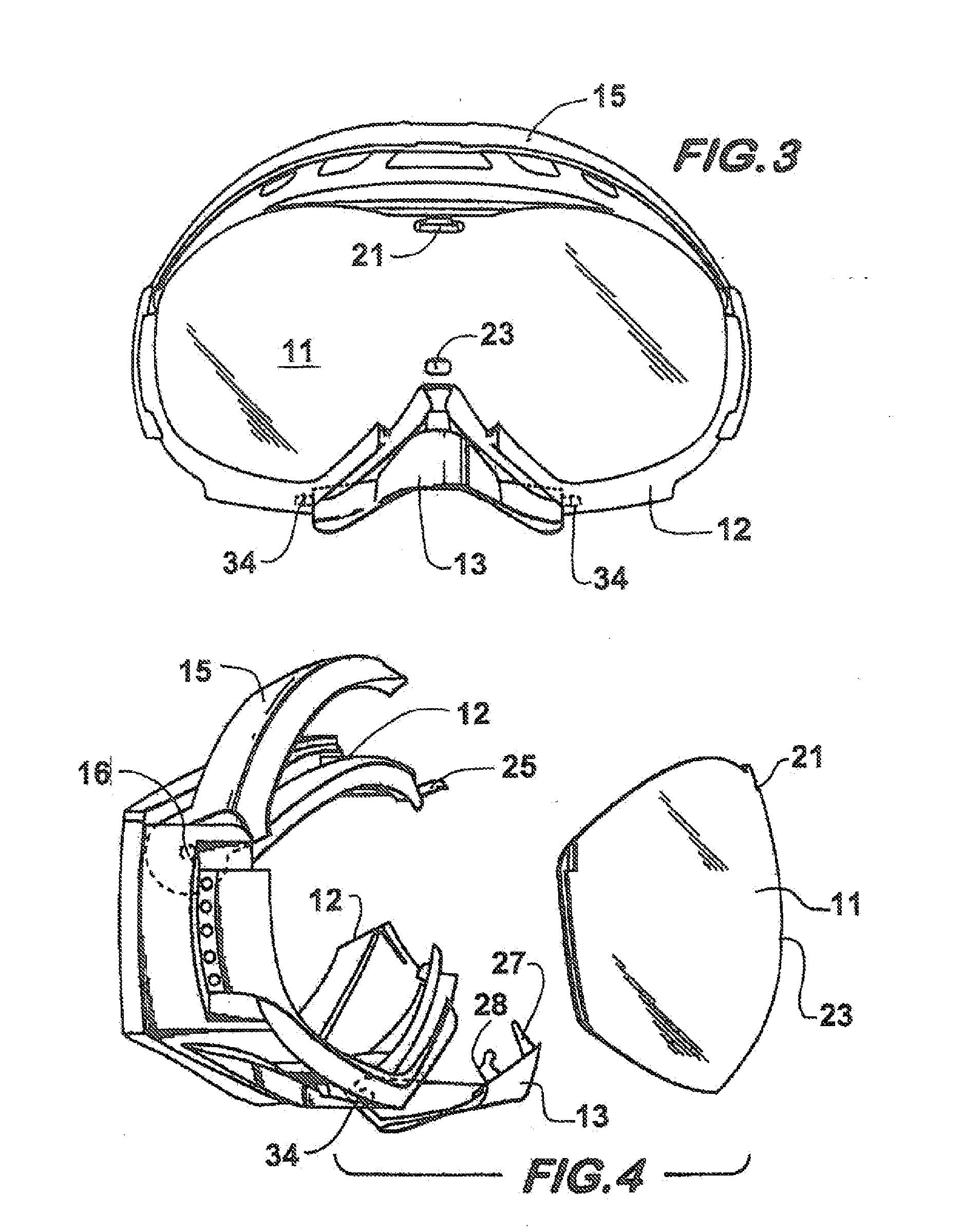
[0010]In order to meet the needs in the art described above, the present goggles have been devised. In one embodiment, a full-coverage pair of goggles protects the eyes of the wearer and includes a continuous contoured inner perimeter of its frame which is adapted to fit snugly against the wearer's face at all points. The present invention utilizes a substantially rigid frame with separate top and bottom elements, one or both of which may be individually rotatable, namely an upper browbar and a lower nosepiece, that firmly capture the lens from above and below. The lens is further secured to the frame by projections on each of the browbar and nosepiece which fit through apertures in the lens. At the top, a post which projects forwardly from the frame is received in the well of the browbar by snap-fit engagement. At the bottom, a prong on the nosepiece passes through a bottom aperture of the lens and is received in a recess of a bottom portion of the frame by snap-fit engagement. The apertures and cooperating projections are preferably located along the center of a one-piece lens. Thus, the rotatable browbar and nosepiece capture the lens top and bottom by edgewise compression as well as securely holding the lens front-to-back through the lens apertures. This system provides a means of mechanically attaching the lens that permits the quick and easy release of the lens from the frame yet providing secure attachment of the lens to the frame when the browbar and nosepiece are in their closed and locked positions.
[0011]In one embodiment of the invention used for skiing, side portions of the frame include vent holes on the side portions which allow the free flow of ambient air to the interior of the goggles behind the lens. Furthermore, the lens may be of a two-layer type in which a front and back lens plate is separated by a gap to create an air space which serves to thermally insulate the inside surface of a lens to help prevent fogging.
[0012]It is therefore an object of the invention to provide a sport goggle such as ski goggles which provide ease of lens interchangeability in a rugged structure which can resist a violent impact without damage or breakage. It is a further object of the invention to provide a pair of ski goggles with an interchangeable lens system which is easy and quick requiring minimal dexterity of the user. Further objects and advantages will become apparent from the following further description and drawings which depict a preferred embodiment.

Problems solved by technology

The lens portion of the goggles receives the greatest amount of wear and damage and they regularly become scratched and broken.
This often occurs in sporting applications where the user falls while wearing the goggles or when the lens becomes scratched or cracked, therefore needing replacement.
This is a difficult and time-consuming procedure which is hard to perform without a tool other than one's fingers.
This can be even more frustrating when the lens removal and replacement needs to be accomplished outdoors where tools are not available.
The problem with this design, however, is that the lens is not sufficiently supported, and firm capture of the lens within the frame members is dependent upon excessive compression from the frame elements which often loosen, leading to a loss of sufficient grip on the lens.
While such eyewear provides an easily interchangeable lens, it does not provide adequate eye protection or stability required of sports ski goggles.

Method used


Image

  • Goggles with interchangeable lens
  • Goggles with interchangeable lens
  • Goggles with interchangeable lens

Examples


Embodiment Construction

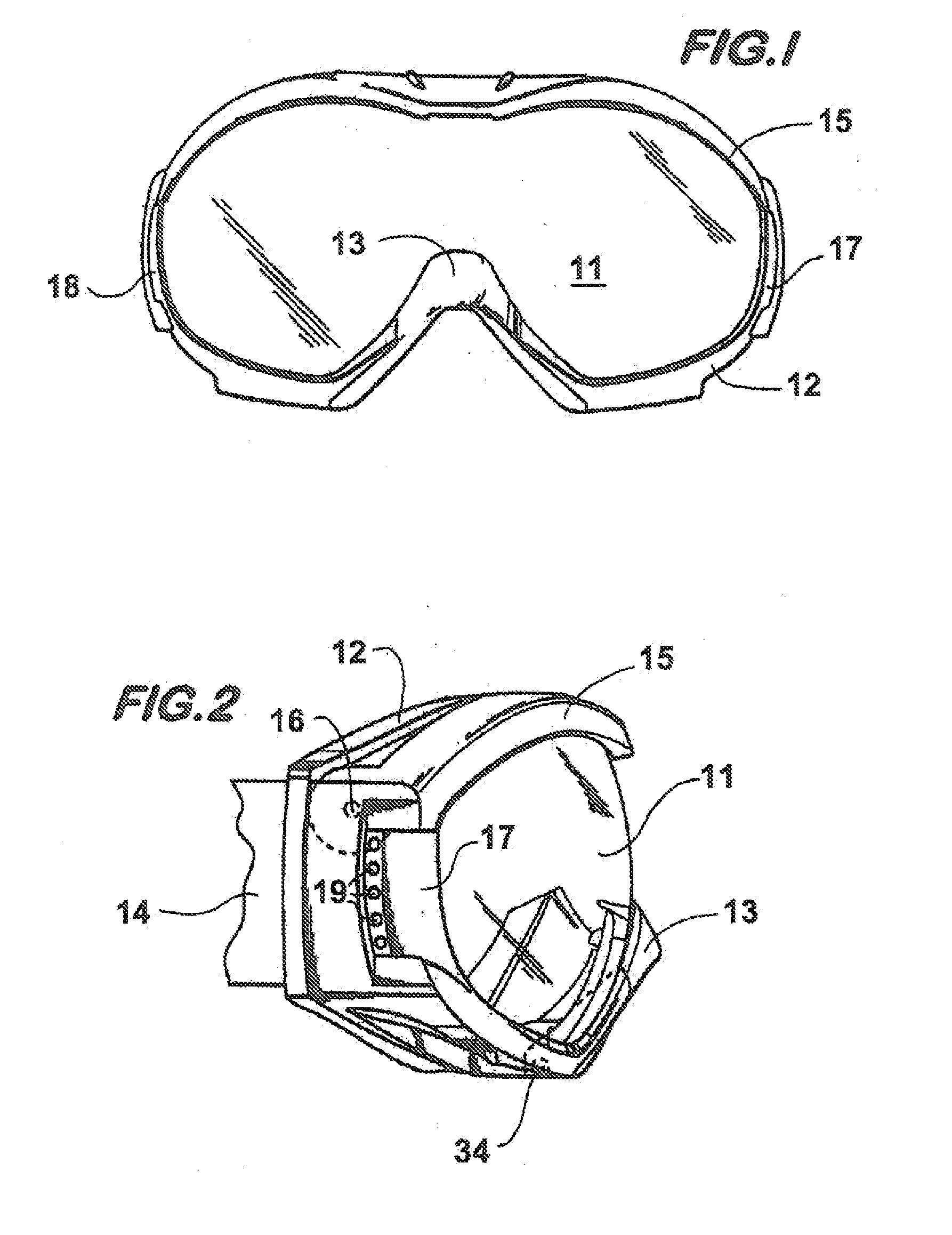
[0024]Referring now to FIG. 1, an embodiment of the present invention depicted is a pair of ski goggles which include the basic elements of a substantially rigid frame 12 which holds a lens 11. As will be further described herein, the lens is secured by rotatable elements browbar 15 and nosepiece 13. Ventilation ducts 17 and 18 provide ventilation for the interior of the goggles.

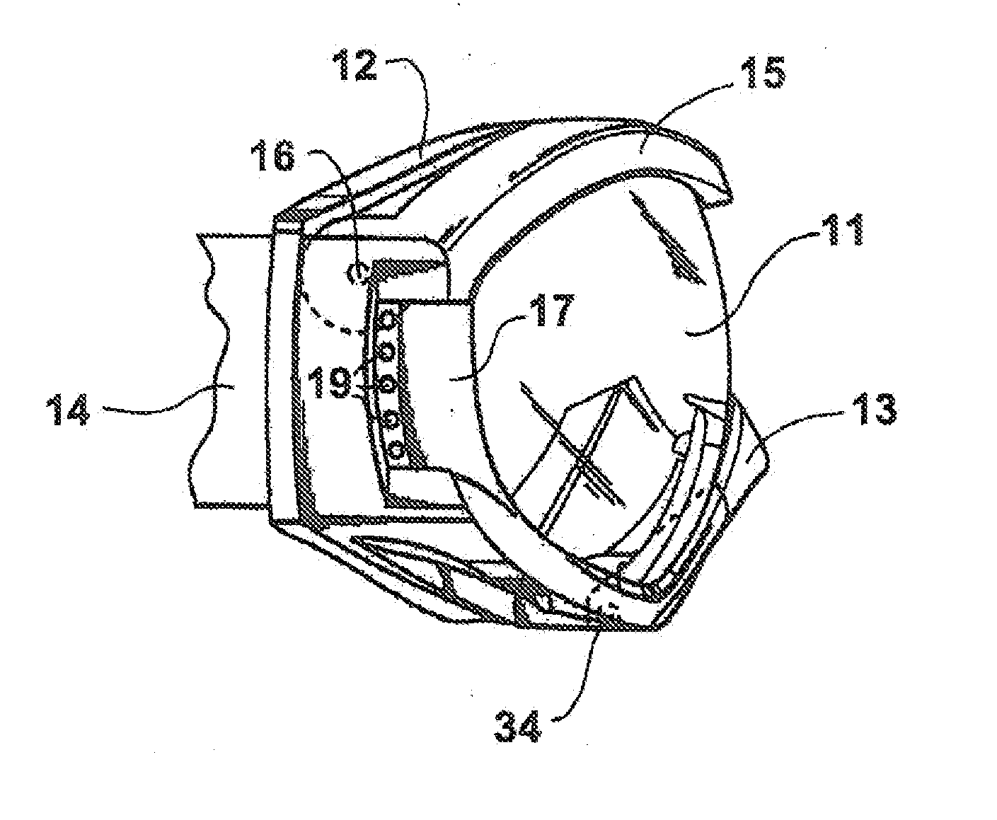
[0025]Referring now to FIG. 2, only the right side region is shown in this figure but it is sufficient to fully depict the embodiment since the goggles are substantially symmetrical about a vertical centerline through the lens 11, the left side being a mirror image of the right side. The browbar 15 is rotatably affixed to frame 12 by way of a pin hinge 16 at side regions of the frame. Nosepiece 13 is likewise rotatably affixed to frame 12 at a bottom portion of the frame. The nosepiece is rotatably affixed to the frame by way of laterally projecting axles 34 on either side of the nosepiece. The axles 34 are ...


PUM


Abstract

The goggles of the invention utilize a substantially rigid frame with separate top and bottom individually rotatable elements, namely an upper browbar and a lower nosepiece, that firmly capture the lens from above and below. The lens is further secured to the frame by projections on each of the browbar and nosepiece which fit through apertures in the lens. At the top, a post which projects forwardly from the frame is received in the well of the browbar by snap-fit engagement. At the bottom, a prong on the rotatable nosepiece passes through a bottom aperture of the lens and is received in a recess of a bottom portion of the frame by snap-fit engagement. The apertures and cooperating projections are preferably located along the center of a one-piece lens. Thus, the rotatable browbar and nosepiece capture the lens top and bottom by edgewise compression and hold the lens front-to-back.

Description

CLAIM OF PRIORITY[0001]The present application is a continuation-in-part application of previously filed, now pending application having Ser. No. 11 / 779,331 on Jul. 18, 207 which is set to mature as U.S. Pat. No. 7,856,673 on Dec. 28, 2010, incorporated herein by reference.BACKGROUND OF THE INVENTION[0002]1. Field of the Invention[0003]The present invention relates in general to sports goggles such as goggles for skiing, off-road motorcycling (MX), snowboarding and ATV riding. More specifically, it relates to a pair of snow or MX goggles with pivoting upper and lower members mounted on a frame that enables the lens to be easily removed and replaced.[0004]2. Description of the Related Art[0005]In recent years there has been a tremendous growth in the use of protective, safety and sports eyewear. Examples are ski goggles and safety glasses worn in industrial settings. The lens portion of the goggles receives the greatest amount of wear and damage and they regularly become scratched an...

Claims


Application Information

Patent Timeline
Patent Type & Authority Applications(United States)
IPC IPC(8): A61F9/02
CPCA61F9/025
Inventor REED, RUSSELLMARKOVITZ, AARON
Owner CROSS OPTICAL GROUP
Learn More