Modulated air flow clothes dryer and method

a dryer and module technology, applied in the field of clothes dryers, can solve the problems of linen or textile damage, waste of energy, etc., and achieve the effect of reducing energy consumption, reducing drying time, and reducing waste of energy

Inactive Publication Date: 2011-11-24
PELLERIN MILNOR
View PDF5 Cites 13 Cited by
  • Summary
  • Abstract
  • Description
  • Claims
  • Application Information

AI Technical Summary

Benefits of technology

[0011]In a case where the linen blocks the air flow, the vacuum in the dryer housing rapidly increases. Responsive to this rapid increase in vacuum, the speed of the suction blower is reduced. The speed reduction of the suction blower lowers the vacuum, eliminating the blockage. A control feedback loop can be used to reduce the rotation speed of the blower and eliminate the blockage.
[0012]By measuring the rate of change of the vacuum, a software algorithm can predict when linen is about to block the air flow thereby eliminating the condition before it occurs. By preventing the linen from beginning to block the air flow, the linen is maintained in an optimum suspension in the heated air stream within the chamber.
[0014]Energy is further saved because drying time is shortened by keeping the clothes or linen in the optimum suspension in the heated air stream thereby efficiently using the heated air.
[0015]Energy is also saved by never allowing a blockage of the air stream. Thus, drying time is shortened.

Problems solved by technology

This condition can result in linen or textile damage and a waste of energy.

Method used


Image

  • Modulated air flow clothes dryer and method
  • Modulated air flow clothes dryer and method

Examples


Embodiment Construction

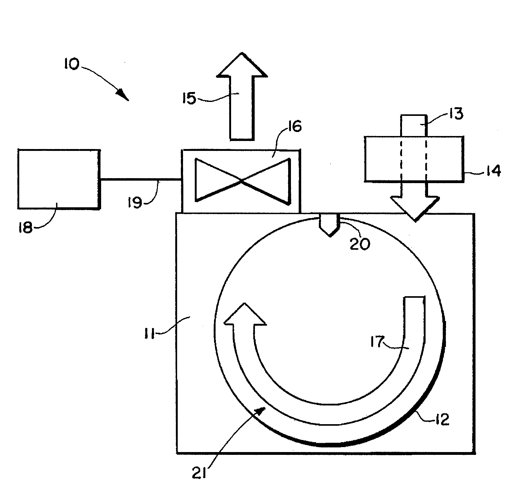
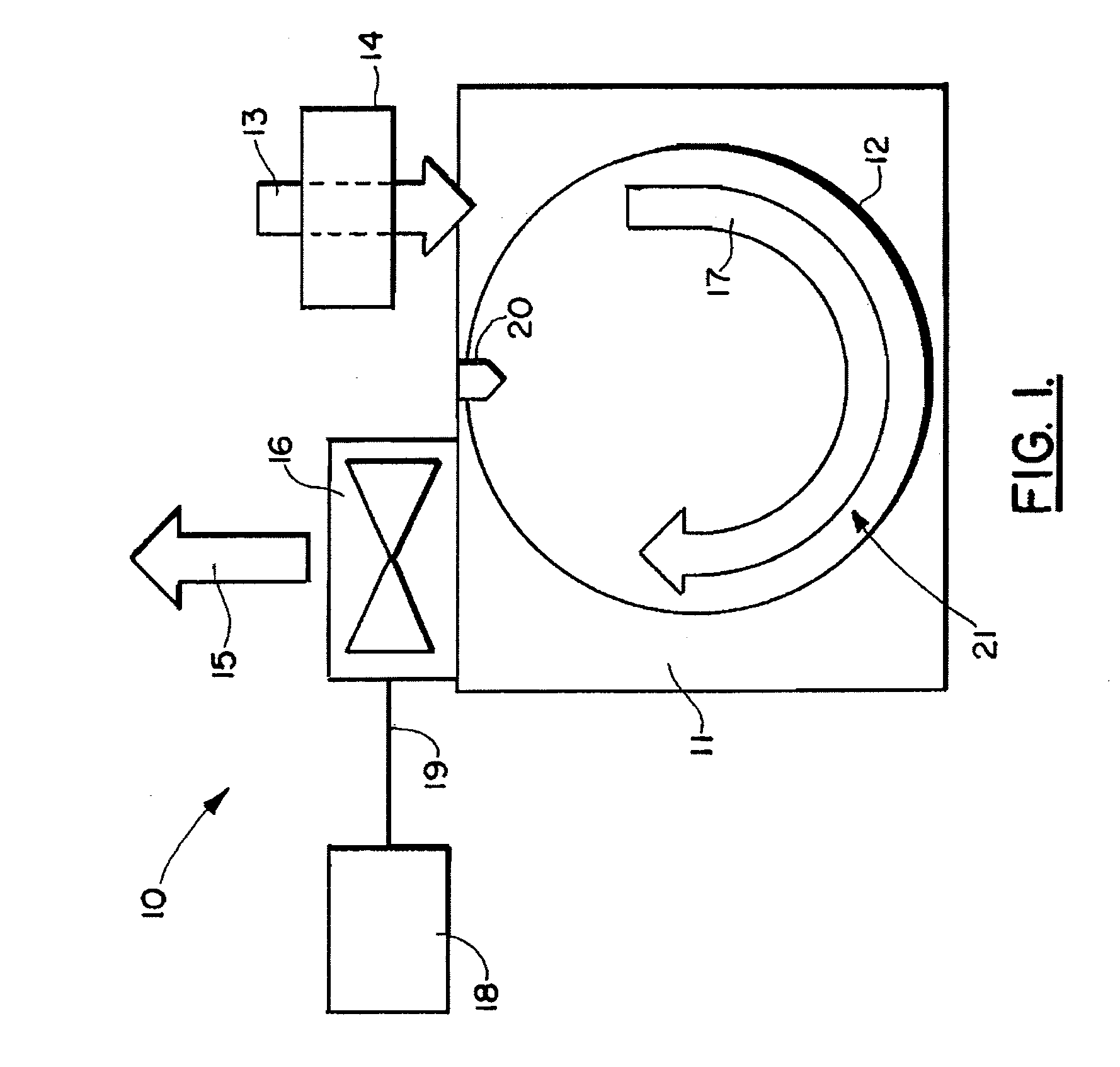
[0018]FIG. 1 shows a preferred embodiment of the apparatus of the present invention, designated generally by the numeral 10. Clothes dryer apparatus 10 provides a dryer housing, frame, or chassis 11. The dryer housing, frame, or chassis 11 supports a drum 12 that can be a rotating drum. Dryer housing 11 provides an opening that can be closed with a door for adding previously washed, wetted textile articles such as clothes or linen to a drum 12 so that those wetted articles can then be dried. Textiles as used herein refers to any washable fabric article.

[0019]A main air inlet 13 enables air to enter a drying chamber 21 within drum 12. Heater 14 can be placed next to or upon frame 11 at main air inlet 13. In this fashion, heat transfer from heater 14 can be used to heat air that enters dryer chamber 21 via main air inlet 13.

[0020]A main air outlet 15 is provided for exhausting air from drying chamber 21. Suction blower 16 is placed in a position next to or attached to frame 11 as show...


PUM


Abstract

A textile articles dryer provides a chassis or housing supporting a rotating drum. A main air inlet enables air to enter the rotating drum. A main air outlet enables air to exit the rotating drum. A vacuum blower pulls a main airflow stream in between the main air inlet and the main air outlet. A heater is in communication with the main airflow stream for heating the air in the main flow stream. A controller maintains a generally constant vacuum in the rotating drum by lowering blower speed responsive to a blockage or near blockage of the main air outlet by one or more textile articles that are being dried.

Description

CROSS-REFERENCE TO RELATED APPLICATIONS[0001]Priority of U.S. Provisional Patent Application Ser. No. 61 / 224,986, filed 13 Jul. 2009, incorporated herein by reference, is hereby claimed.STATEMENT REGARDING FEDERALLY SPONSORED RESEARCH OR DEVELOPMENT[0002]Not applicableREFERENCE TO A “MICROFICHE APPENDIX”[0003]Not applicableBACKGROUND OF THE INVENTION[0004]1. Field of the Invention[0005]The present invention relates to clothes dryers and a method of operating a clothes dryer. More particularly, the present invention relates to an improved method and apparatus for drying clothes wherein a suction blower pulls air from a dryer chamber to create a vacuum within the dryer chamber, the vacuum generated by the suction blower being controlled (e.g., computer, controller) in response to the rate of change of increasing or decreasing vacuum within the chamber. The method further includes the adjusting of the speed of the blower to maintain a constant vacuum such as in cases of a rapidly incre...

Claims


Application Information

Patent Timeline
Patent Type & Authority Applications(United States)
IPC IPC(8): F26B3/02F26B21/06D06F58/04
CPCD06F58/28D06F2058/2858F26B21/12F26B11/04D06F2058/2864D06F58/50D06F2103/30D06F2103/36D06F2103/54D06F2105/18D06F2105/24D06F2105/30
Inventor POY, RUSSELL H.
Owner PELLERIN MILNOR
Why Eureka
Try Eureka