Auxiliary welding heating system

a heating system and welding technology, applied in the field of welding or cutting systems, can solve the problems of increased welding cost, increased welding time, weld distortion, etc., and reduce welding productivity (e.g., welding speed)

Active Publication Date: 2011-11-24
ILLINOIS TOOL WORKS INC
View PDF14 Cites 58 Cited by
  • Summary
  • Abstract
  • Description
  • Claims
  • Application Information

AI Technical Summary

Problems solved by technology

Unfortunately, as the thickness of the plates to be welded increases, welding time, welding consumables, weld distortion, and cost of plate preparation increase, while welding productivity (e.g., welding speed) decreases.
All of these arrange

Method used


Image

  • Auxiliary welding heating system
  • Auxiliary welding heating system
  • Auxiliary welding heating system

Examples


Embodiment Construction

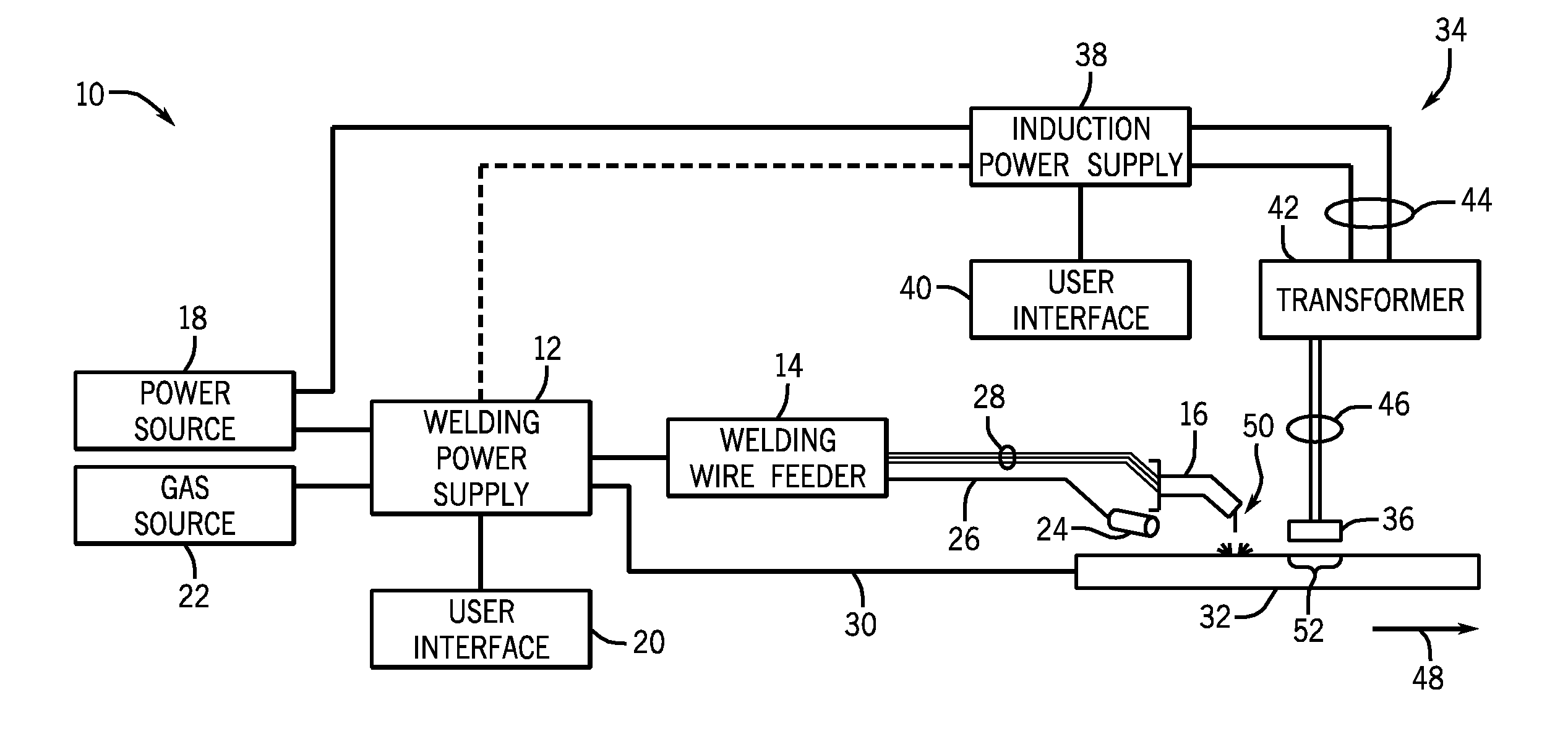
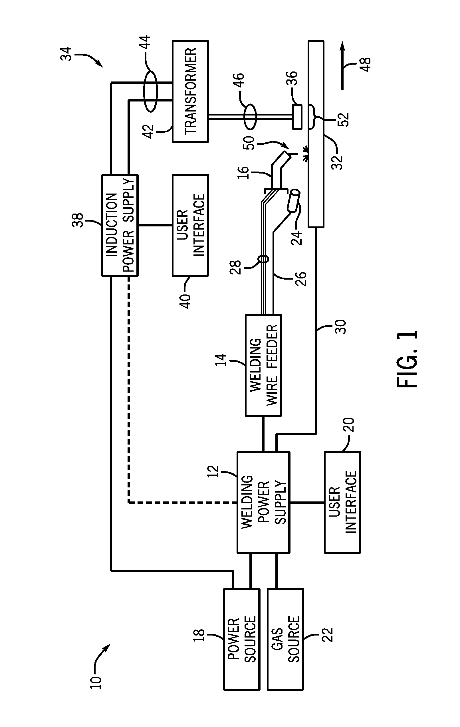
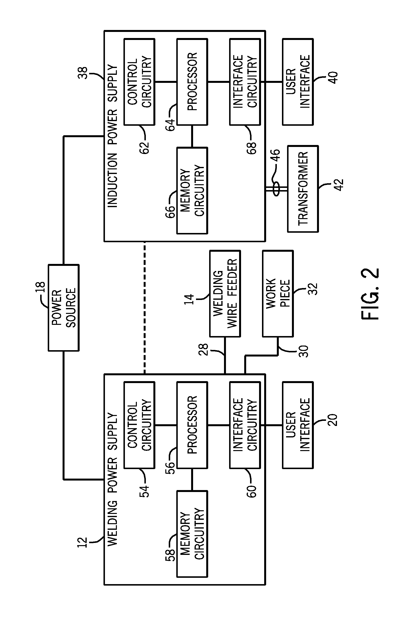
[0015]As described in detail below, embodiments of an induction heating system configured to heat a weld location ahead of an arc welding process are described. The induction heating system is adapted to heat a local area of a weld joint to elevated temperatures just before the welding arc reaches the weld location. The heat produced by the welding arc is then used to bring the work piece above the melting point and to melt the welding wire electrode. As a result, the welding process can proceed at a faster rate, and / or with more penetration and / or with better mechanical characteristics thereby increasing the productivity and / or quality of the welding process. Moreover, heating is performed much more locally than with previous induction heating techniques. The induction heating system includes an induction heating coil that is positioned near the surface of the work piece to be welded and adjacent to a welding torch. An alternating current produced by a power supply flows through th...


PUM

PropertyMeasurementUnit
Temperatureaaaaaaaaaa
Heightaaaaaaaaaa

Abstract

An auxiliary welding heating system includes an induction heating coil disposed adjacent to a welding torch or plasma cutter. The auxiliary welding heating system further includes an induction power supply configured to generate an alternating current and a step-down transformer coupled to the induction power supply. The induction heating coil is coupled to the step-down transformer and is configured to receive the alternating current and induce eddy currents in a welding work piece to heat the welding work piece before an advancing welding arc or plasma cut to a homologous temperature of at least approximately 0.5.

Description

CROSS REFERENCE TO RELATED APPLICATIONS[0001]This application is a Non-Provisional patent application of U.S. Provisional Patent Application No. 61 / 346,961 entitled “High Deposition Arc Welding”, filed May 21, 2010, which is herein incorporated by reference.BACKGROUND[0002]The invention relates generally to welding or cutting systems, and, more particularly, to an induction heating system for a welding or cutting process.[0003]Welding is a process that has become increasingly ubiquitous in various industries and applications. Such welding operations are used for many types of heavy fabrication in various environments both in-shop as well as in the field. For example, welding operations may be used to fabricate pipelines, bridges, building structures, oil production facilities, petroleum storage tanks, water towers, and many other structures and components. Moreover, a wide range of metals having various compositions, sizes, geometries, and so forth may be formed or joined using weld...

Claims


Application Information

Patent Timeline
IPC IPC(8): H05B6/04
CPCB23K9/1006B23K9/32B23K9/235
Inventor HOLVERSON, TODD EARLJONES, JERALD EDWARDRHOADES, VALERIE LISAMADDEN, STEPHEN KING
Owner ILLINOIS TOOL WORKS INC
Why Eureka
Try Eureka