Fluorescence microscopy imaging system

a fluorescence microscope and imaging system technology, applied in the field of fluorescence microscopy imaging system, can solve the problems of limited magnification power of optical microscope, large volume of fluorescence microscope, and inconvenient carrying

Active Publication Date: 2011-11-24
IND TECH RES INST
View PDF2 Cites 13 Cited by
  • Summary
  • Abstract
  • Description
  • Claims
  • Application Information

AI Technical Summary

Benefits of technology

[0014]In another aspect, according to an embodiment of the present invention, the fluorescence microscopy imaging system further comprises a servo control system architecture using a triaxial actuator to perform planar scanning and focusing servo function on the sample.

Problems solved by technology

An early microscope technology is an optical microscope that uses visible light to observe a target; however, the magnifying power of the optical microscope is limited due to wavelengths of visible light.
In issued U.S. Pat. No. 7,639,420, a fluorescence microscope is disclosed, but the fluorescence microscope has a large volume and is not convenient to carry.
The microscope is focused through an eyepiece, which is not convenient to use.

Method used


Image

  • Fluorescence microscopy imaging system
  • Fluorescence microscopy imaging system
  • Fluorescence microscopy imaging system

Examples


Embodiment Construction

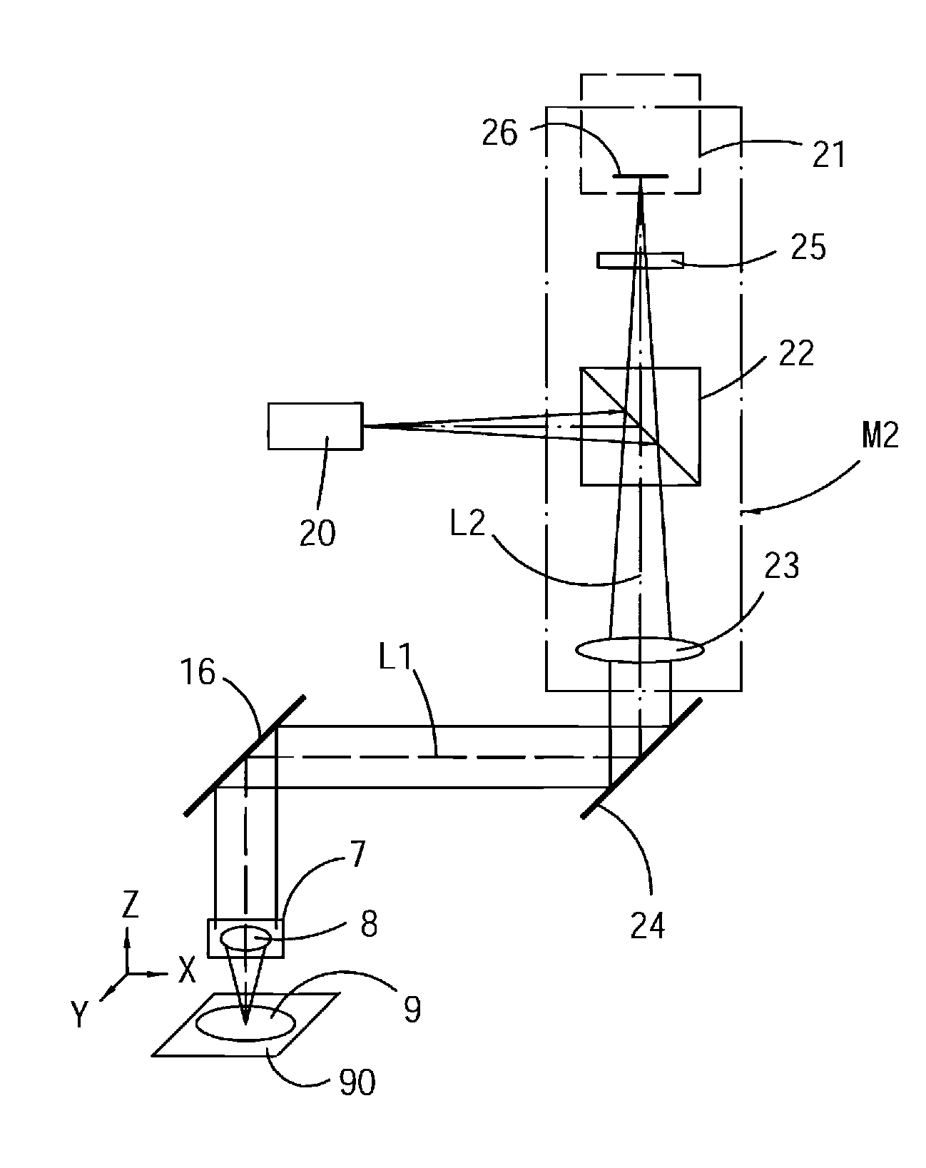
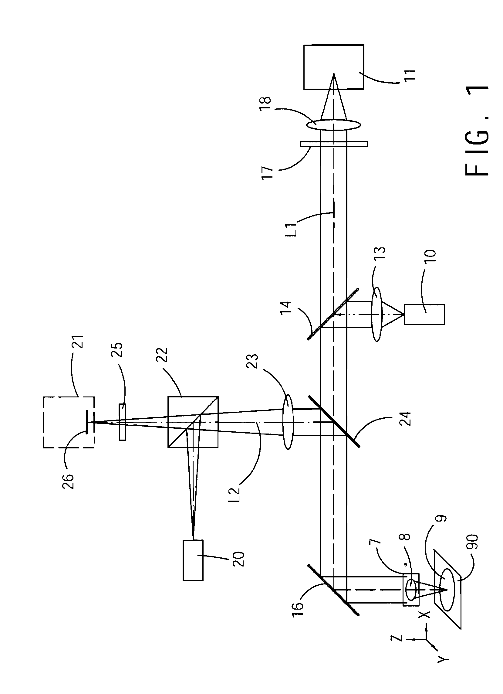
[0026]FIG. 1 shows implementation architecture of a fluorescence microscopy imaging system according to an embodiment, which includes a module for detecting fluorescence and a module for focusing control.

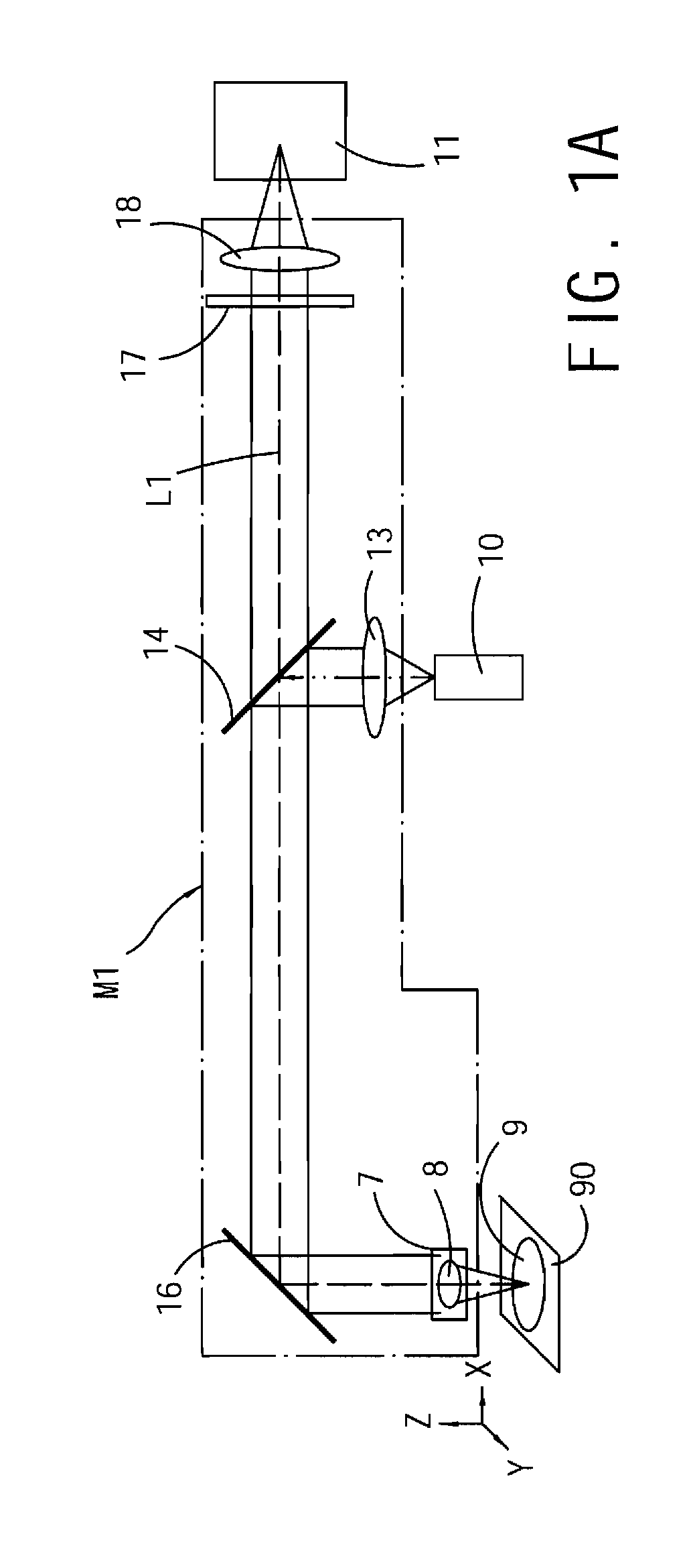
[0027]Referring to FIG. 1A, the module for detecting fluorescence has a fluorescence excitation light source generator 10, an optical assemble module of fluorescence detection M1, and a fluorescence detector 11. The fluorescence excitation light source generator 10 is capable of generating an excitation light beam having a first wavelength to excite a sample 9 to emit fluorescence. The excitation light beam is guided by the optical assemble module of fluorescence detection M1 along a light path L1 to pass through an objective 8 and focused on the sample 9 so as to excite the sample 9 to emit fluorescence light, and then the excited fluorescence light of the sample 9 is guided by the optical assemble module of fluorescence detection M1 along the light path L1 to the fluorescence dete...


PUM


Abstract

A fluorescence microscopy imaging system is used for detecting a fluorescence signal of a sample, and includes a module for detecting fluorescence and a module for focusing control. The module for detecting fluorescence includes a fluorescence excitation light source generator (FELSG) and a fluorescence detector. The FELSG is capable of generating an excitation light beam having a first wavelength to excite the sample to emit fluorescence. The fluorescence detector is used to read the fluorescence signal of the sample. The module for focusing control generates a servo light beam having a second wavelength. A servo light beam reflecting film disposed on an observation plane is used to reflect the servo light beam. A return beam signal is analyzed using a focusing detection method. An actuator is used to move the objective for focusing, so as to enable the fluorescence excitation light beam to excite the sample to emit fluorescence.

Description

CROSS-REFERENCE TO RELATED APPLICATIONS[0001]This non-provisional application claims priority under 35 U.S.C. §119(a) on Patent Application No(s). 099116015 filed in Taiwan, R.O.C. on May 19, 2010, the entire contents of which are hereby incorporated by reference.BACKGROUND[0002]1. Technical Field[0003]The present invention relates to a fluorescence microscopy imaging system, and more particularly to a fluorescence microscopy imaging system having a focusing servo function.[0004]2. Related Art[0005]An early microscope technology is an optical microscope that uses visible light to observe a target; however, the magnifying power of the optical microscope is limited due to wavelengths of visible light. Currently, a fluorescence microscope combining a laser light source with a fluorescence technology is used in further combination with computer image analysis, so as to further observe detailed internal structures of a tissue; while through a confocal microscope, z-axis control can be fu...

Claims


Application Information

Patent Timeline
Patent Type & Authority Applications(United States)
IPC IPC(8): G02B7/04G01J1/58
CPCG02B21/245G02B21/16
Inventor WU, PING JUNGCHENG, KUEN CHIUANYU, HSING CHENGJU, JAU JIUHUANG, CHUN CHIEHLEE, YUAN CHIN
Owner IND TECH RES INST
Why Eureka
Try Eureka