Television broadcast receiving apparatus

a technology for receiving apparatus and television, applied in the direction of color television details, television systems, automatic control, etc., can solve the problems of increasing the number of mounted parts, unable to completely eliminate abnormal sound, and inhibiting the achievement of less expensive equipment, so as to achieve enhanced practical sound sensitivity, avoid abrupt break in sound, and reduce the effect of cos

Inactive Publication Date: 2011-11-24
SHARP KK
View PDF4 Cites 8 Cited by
  • Summary
  • Abstract
  • Description
  • Claims
  • Application Information

AI Technical Summary

Benefits of technology

[0026]According to the present invention, in response to an out-of-synchronization flag signal from a phase synchronization loop part, a sound detecting part outputs a noise signal of a predetermined level instead of an audio signal, thereby achieving muting of a sound concurrently with complete loss of picture for viewing. In addition, because the noise signal causes a natural noise sound to be outputted, an abrupt break in a sound can be avoided. Therefore, enhanced practical sound sensitivity can be achieved at low cost.

Problems solved by technology

There has been a problem that detection of this noise by FM detecting part 608 turns the noise into a sound noise, which is outputted from a speaker of an television broadcast receiving apparatus as an abnormal sound offensive to the ear.
The countermeasures described above also cause some inconvenience.
Specifically, although addition of filter 800 against the abnormal sound has achieved reduction of the abnormal sound due to the noise in the IF signal and provided a certain effect, increase of mounted parts in number and use of an expensive filter because of steep frequency characteristics have inhibited achieving less expensive equipment.
Further, addition of a filter could not completely eliminate the abnormal sound.
In addition, as for reception of analog broadcasting, even when a smaller input signal to a receiver causes lower picture sensitivity that does not meet a practical level for watching, sound sensitivity may remain at its sufficiently practical level.
The countermeasure as described above of muting a sound in response to loss of synchronization of a vertical synchronization signal at decode and output unit 400, however, has a drawback of causing no sound output even in a state in which a smaller input signal to the receiver causes somewhat disturbed synchronization of a picture, which results in lower practical sound sensitivity.
Therefore, the circuit configuration and control of the signals is rather complex and not suitable for achieving less expensive apparatus.
In addition, it cannot be said that consideration is given to a sound mute operation in the case of increased or decreased input signal level to the apparatus.
In this case, although noise reduction can be effectively achieved, setting output of audio data zero depending on the condition of reception makes occurrence of no-sound state unavoidable, and therefore, an abrupt break in a sound is experienced in the vicinity of the reception limit.

Method used


Image

  • Television broadcast receiving apparatus
  • Television broadcast receiving apparatus
  • Television broadcast receiving apparatus

Examples


Embodiment Construction

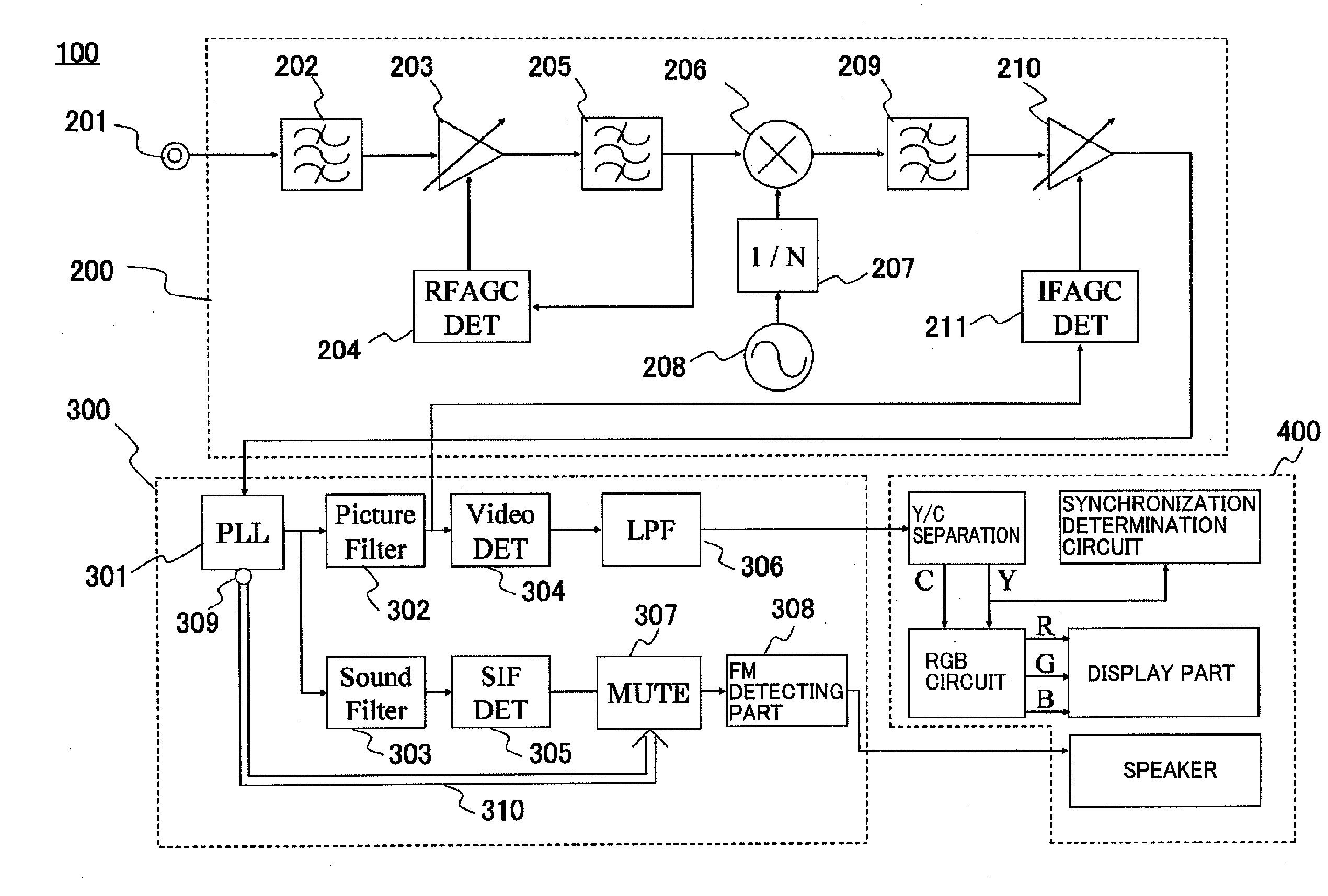
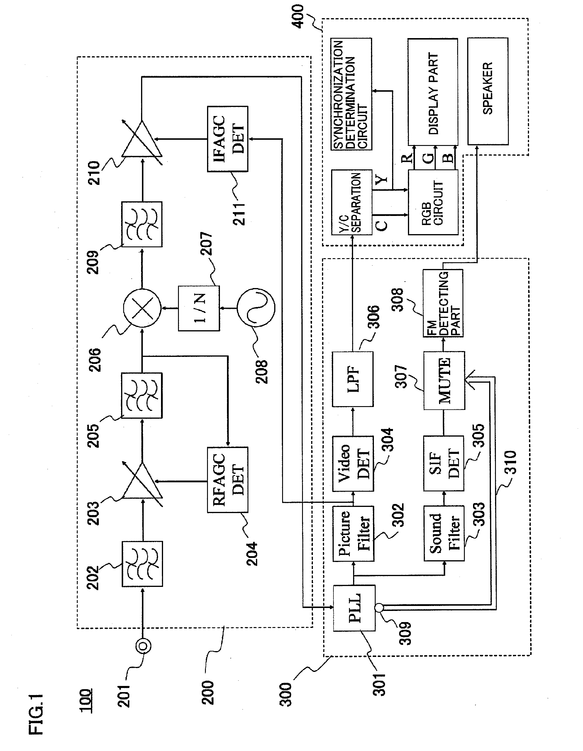
[0032]A television broadcast receiving apparatus 100 according to one embodiment of the present invention includes a tuning unit 200, a demodulating unit 300 and a decode and output unit 400, as shown in FIG. 1. It is noted that the configuration and operation of tuning unit 200 are the same as those of the tuning unit shown in FIG. 4, and a description thereof will not be repeated. Description will be given of a process in which an IF signal is outputted from tuning unit 200 and processed at demodulating unit 300 to be converted into a video signal and an audio signal which are demodulated signals.

[0033]An IF signal outputted from tuning unit 200 is inputted to a PLL part 301 of demodulating unit 300. PLL part 301 regulates the phase of the IF signal such that the phase of the IF signal and the phase of a carrier signal generated within PLL part 301 are in agreement. PLL part 301 has a mute control terminal 309. The IF signal phase regulated by PLL part 301 is supplied in parallel ...


PUM


Abstract

A television broadcast receiving apparatus has a demodulating unit including a PLL part synchronizing a phase of an IF signal with a phase of an internally generated carrier signal and outputting an out-of-synchronization flag signal when the IF signal and the carrier signal are in an unsynchronized state, and a muting part muting a sound intermediate frequency signal and outputting a noise signal of a predetermined level when the out-of-synchronization flag signal is outputted from the PLL part. Therefore, even when an IF amplifier of a tuning unit amplifies a noise at the maximum gain when there is no signal, an abnormal sound can be prevented from being outputted from a speaker of a decode and output unit.

Description

[0001]This nonprovisional application is based on Japanese Patent Application No. 2010-115905 filed on May 20, 2010 with the Japan Patent Office, the entire contents of which are hereby incorporated by reference.BACKGROUND OF THE INVENTION[0002]1. Field of the Invention[0003]The present invention relates to a television broadcast receiving apparatus, and particularly to a television broadcast receiving apparatus capable of receiving analog broadcasting.[0004]2. Description of the Background Art[0005]In recent years, the shift of television broadcasting from analog broadcasting to digital broadcasting is underway worldwide. The timing of termination of analog broadcasting, however, differs between countries. Globally, the shift from analog broadcasting to digital broadcasting is expected to complete by around 2015. Therefore, at the present time, manufacturers of a television broadcast receiving apparatus manufacture and sell a receiver which allows for watching both analog broadcast...

Claims


Application Information

Patent Timeline
Patent Type & Authority Applications(United States)
IPC IPC(8): H03L7/00
CPCH04N5/04H04N5/60H04N5/455
Inventor YAMAGUCHI, HIROYUKIITAYA, TSUYOSHI
Owner SHARP KK
Why Eureka
Try Eureka