Marker for a navigation system

Active Publication Date: 2011-11-24
ATESOS ENG
View PDF1 Cites 35 Cited by
  • Summary
  • Abstract
  • Description
  • Claims
  • Application Information

AI Technical Summary

Benefits of technology

One aspect of the present invention is, accordingly, the covering-over of a spherical retroreflecting surface, especially a retroreflecting sphere, with a light-permeable or transparent (i.e., translucent) shell, more specifically in such a manner that the reflecting image, in respect of contour and barycentre location, is substantially uninfluenced by the shell. As a result of the shell according to the invention, the imaging, ideal from a measurement technique point of view, of a light emitted by a light source and reflected by the reflecting surface, in a

Problems solved by technology

Wetting with water disrupts the beam path only insubstantially.
For spherical, especially ball-shaped, surfaces, the known protective foils are unsuitable.
Undefined distortions are produced.
Consequently, the accuracy of the positional determination is limited, especially when marker recognition algorithms based on the detection of the centre of mass are used (see also EP 1 774 922 A1 in this regard).
As mentioned, flat

Method used


Image

  • Marker for a navigation system
  • Marker for a navigation system
  • Marker for a navigation system

Examples


Embodiment Construction

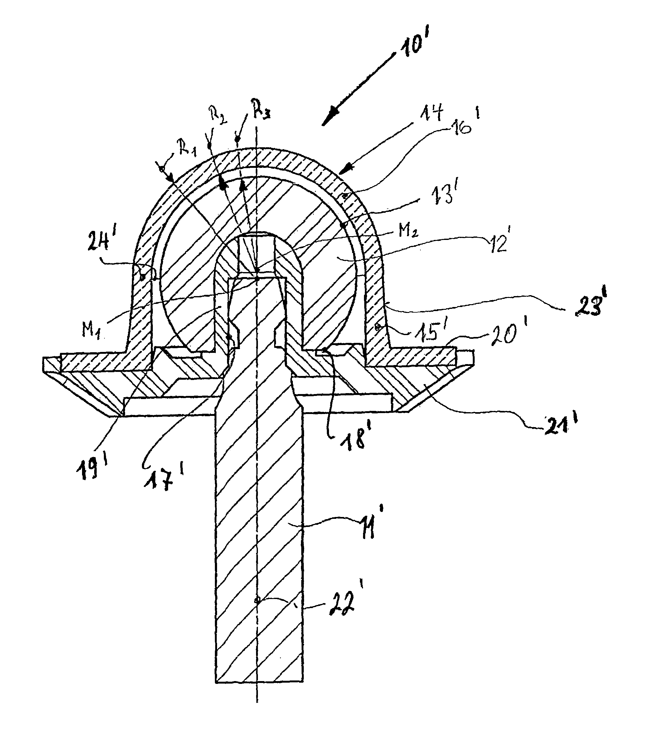
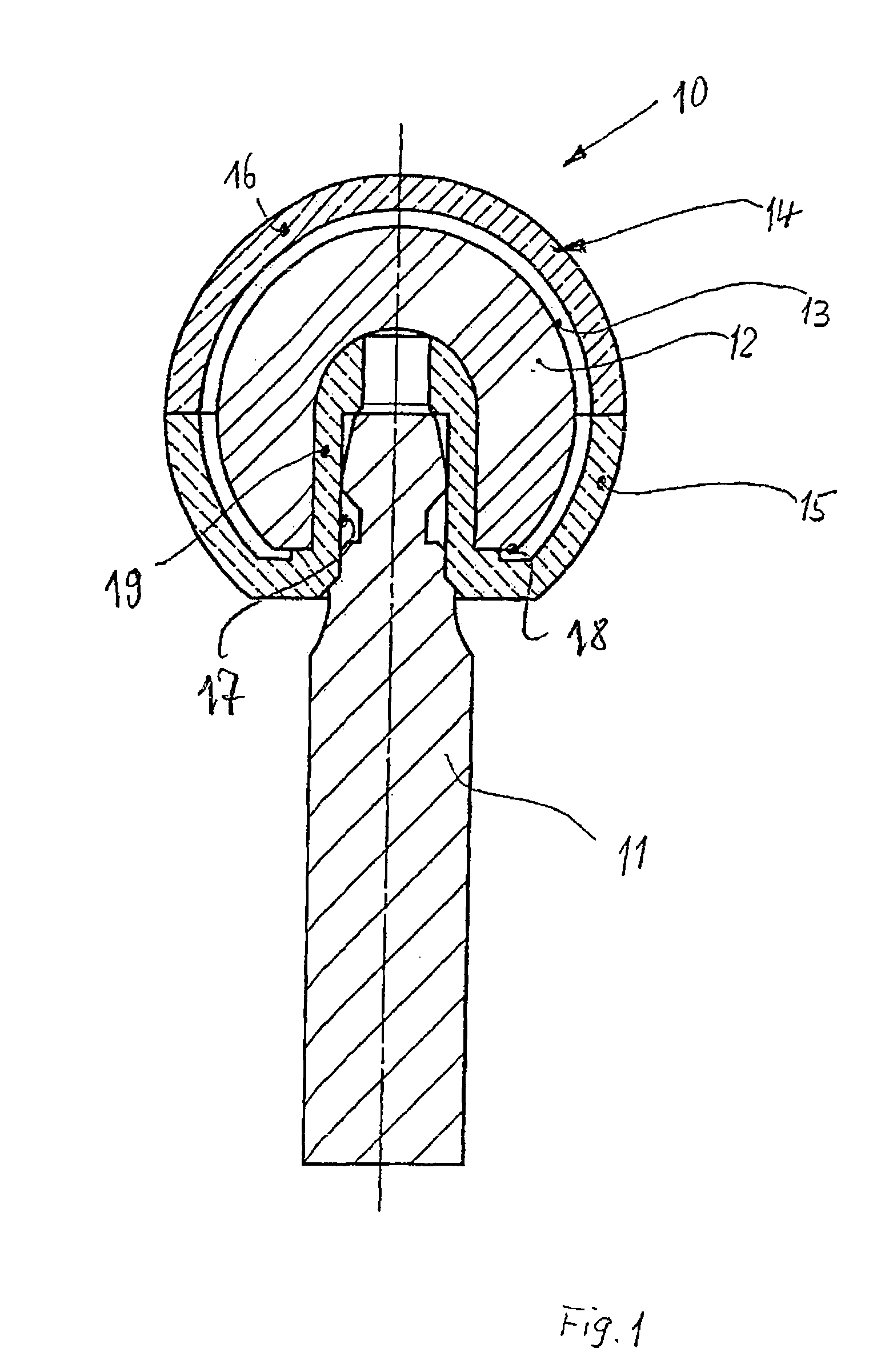
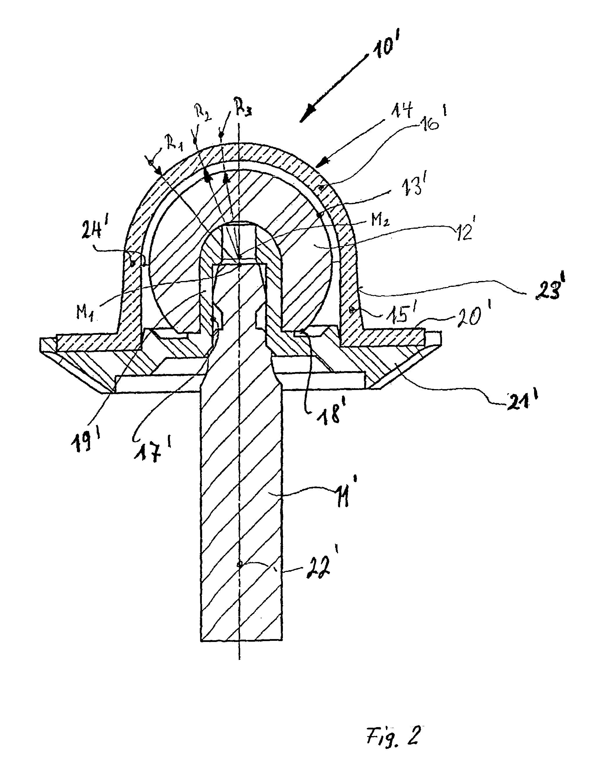
FIG. 1 shows, in longitudinal section and to an enlarged scale, a marker 10 for a navigation system for determining the position in space, of, for example, a surgical instrument. This marker 10 comprises a sphere 12 having a retroreflecting surface 13, which in known manner includes very fine glass spherules having a diameter from 20μ to a maximum of about 200μ. The retroreflecting surface 13 is protected by a dimensionally stable, light-permeable or transparent (i.e., translucent) shell 14, preferably made of transparent plastics material, more specifically in such a manner that the reflected image remains substantially uninfluenced in respect of contour and barycentre location. As mentioned hereinbefore, imaging of the retroreflecting sphere surface by a camera associated with the system ideally is circular. As a result of the fact that the shell 14 concentrically surrounds the retroreflecting sphere surface 13 at a small spacing and also that the wall thickness of the shell 14 is...


PUM


Abstract

A marker for a navigation system for determining the spatial position (e.g., of a surgical instrument), said marker including a retroreflective ball (12). A retroreflective surface (13) of the ball (12) is protected by a dimensionally stable, translucent or transparent shell (14) in such a way that the reflected image remains essentially uninfluenced in terms of contour and the position of the centre of gravity.

Description

BACKGROUNDThe present invention relates to a marker for a navigation system.Markers are used, for example in image-assisted surgical procedures (IGS=Image Guided Surgery), for ascertaining the position of surgical instruments or bodies connected to, for example, a plurality of markers in the form of a reference star, by means of optical detection of the light reflected by the markers, and, on the basis of the ascertained positional information, carrying out a surgical intervention.Surgical navigation systems are accordingly used for measuring geometric variables (usually in a sterile context) in the course of surgical interventions on human beings and animals. A much used measurement technique is, as already mentioned, the positional measurement of optical markers using a light-optical camera system. Either these optical markers are self-illuminating (=active markers) or they reflect light produced by a flash-illumination camera system (=passive markers). On account of the particula...

Claims


Application Information

Patent Timeline
IPC IPC(8): G02B5/132G02B5/12
CPCA61B19/5244A61B19/54A61B2019/5483A61B2019/4868A61B2019/5437A61B2019/0286A61B34/20A61B90/39A61B2050/3015A61B2090/0813A61B2090/3937A61B2090/3983
Inventor HAURI, BERNHARDHAURI, THOMAS
Owner ATESOS ENG
Why Eureka
Try Eureka