Triggered covalent probes for imaging and silencing genetic expression

a covalent probe and gene expression technology, applied in the field of covalent crosslinking of nucleic acid probes, can solve the problems of relying on base pairing to provide both sequence specificity and binding affinity, and both techniques are powerful and widely used. , to achieve the effect of reducing or eliminating reducing the expression of a target gen

Active Publication Date: 2011-11-24
CALIFORNIA INST OF TECH
View PDF5 Cites 23 Cited by
  • Summary
  • Abstract
  • Description
  • Claims
  • Application Information

AI Technical Summary

Benefits of technology

[0021]In some embodiments, methods of silencing or reducing expression of a target gene are provided. A cross-linking probe comprising one or more cross-linkers is hybridized to a silencing-target nucle

Problems solved by technology

Both techniques are powerful and widely used but have significant limitations.
In some situations, one fundamental conceptual weakness shared by c

Method used


Image

  • Triggered covalent probes for imaging and silencing genetic expression
  • Triggered covalent probes for imaging and silencing genetic expression
  • Triggered covalent probes for imaging and silencing genetic expression

Examples


example 1

Nucleic Acid Cross-Linking

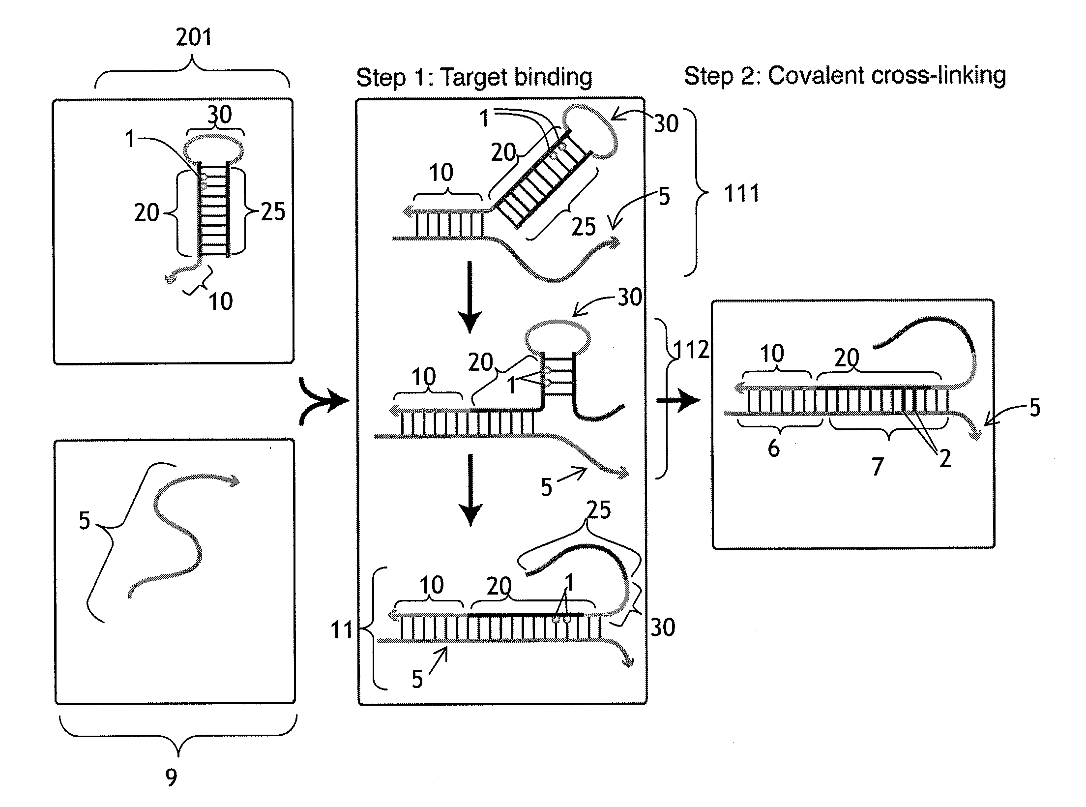
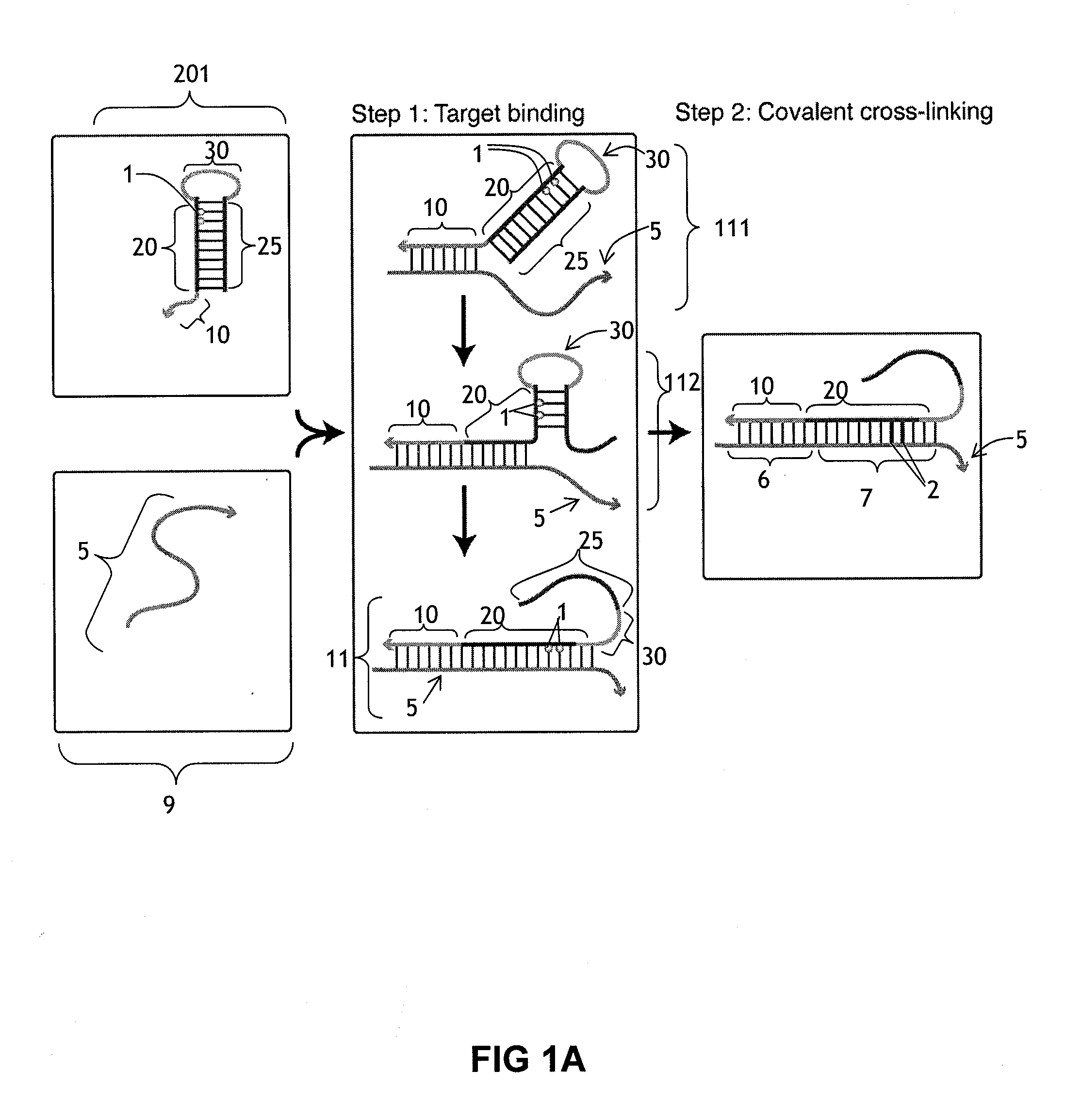
[0188]This example illustrates the use of a cross-linking probe to attach a cross-linker to target nucleic acid, such as an mRNA.

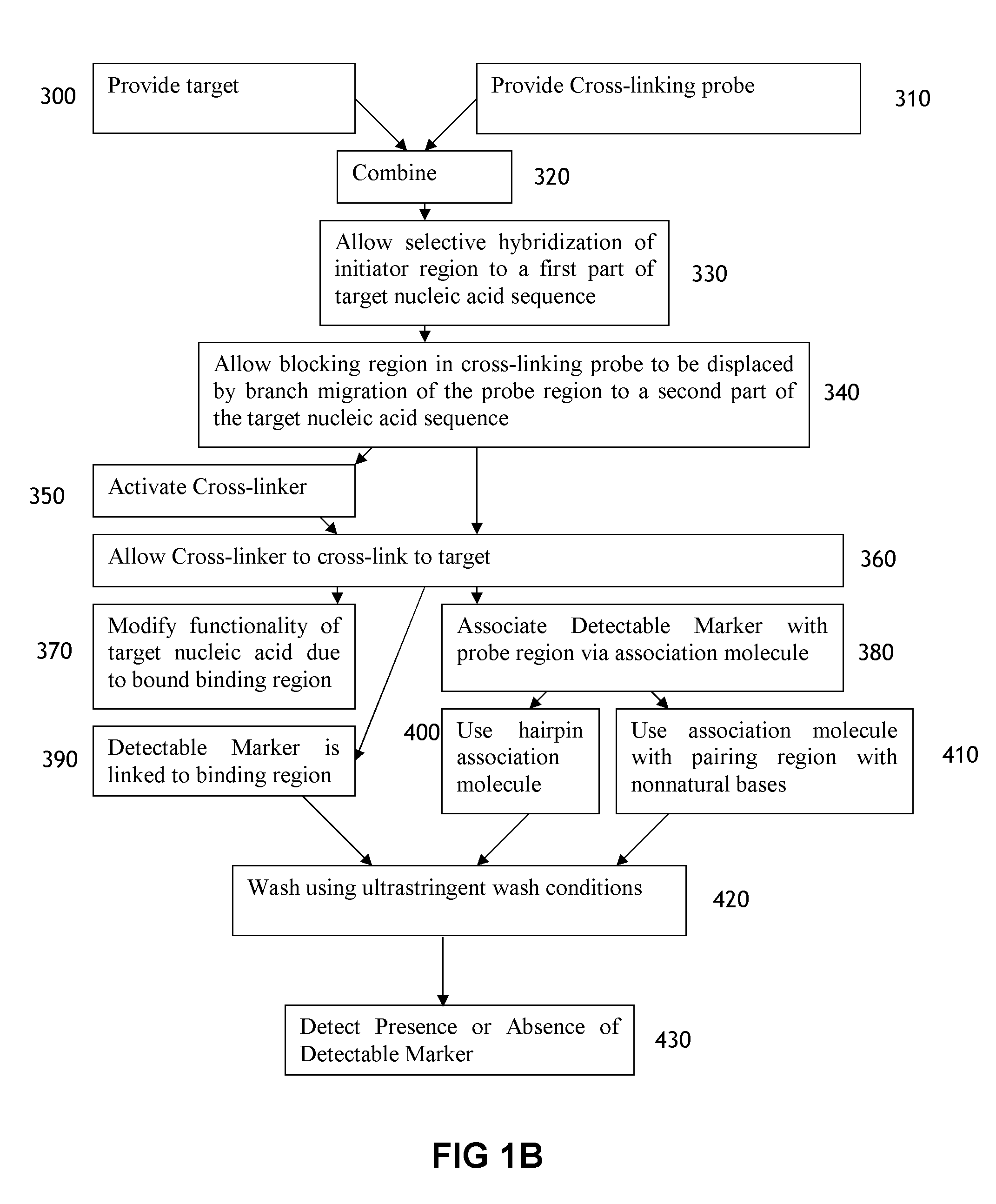
[0189]One first obtains a cross-linking probe that includes an initiator region, a probe region that hybridizes to the desired target nucleic acid, a blocking region that obstructs the cross-linker when bound to the probe region, and a light activatable cross-linker. One then adds the cross-linking probe to the cell or tissue that is believed to include the target nucleic acid and allow the cross-linking probe to hybridize to the target. One then activates the cross-linker by irradiating the cell or tissue. Following this, the cross-linker will cross-link to the target nucleic acid, resulting in a cross-linked target.

example 2

In Situ Hybridization

[0190]This example illustrates a use of a cross-linker probe in an in situ hybridization. One performs the steps outlined in Example 1, except that the cross-linking probe also initially includes a detectable marker region (with one or more detectable markers) that is attached to the blocking region.

[0191]Following irradiation, one then washes the tissue or cell using an ultrastringent wash containing denaturing chemicals such as formamide and / or performing the wash at elevated temperatures. Following this, one then images the remaining detectable markers in the cell or tissue in order to identify whether or not, where, and how much of the target nucleic acid is present.

example 3

mRNA In Situ Hybridization Using a Hairpin Amplifier Molecule

[0192]This example illustrates a use of a cross-linker probe in an in situ hybridization. One performs the steps outlined in Example 2, except that the cross-linking probe also initially includes a pairing region that is attached to the blocking region.

[0193]Following the irradiation, one then washes the tissue or cell via an ultrastringent wash protocol to remove a significant portion of the unbound cross-linking probe. Following this, one then adds the amplifier molecule, which includes a detectable marker region (with decteable markers) and a complementary pairing region that will bind to the pairing region on the cross-linking probe. The amplifer molecule can have the general structure depicted in FIG. 4, and the amplifier molecule can include at least one photoactivatable cross-linker in the complementary pairing region. Following this, one can then irradiate the cell or tissue a second time to cross-link the cross-li...


PUM

PropertyMeasurementUnit
Nucleic acid sequenceaaaaaaaaaa
Lightaaaaaaaaaa

Abstract

The present invention relates to the use of cross-linking probes to covalently bind probes to nucleic acid targets. In some embodiments, the probe comprises an initiator region that is able to bind to a first portion of a target nucleic acid, a probe region linked too the initiator region that is able to bind to a second region of the target nucleic acid and that comprises one or more cross-linkers, and a blocking region hybridized to the probe region.

Description

CROSS-REFERENCE TO RELATED APPLICATIONS[0001]The present application claims priority to U.S. Provisional Application No. 61 / 345,939, filed May 18, 2010, which is hereby incorporated by reference in its entirety.STATEMENT REGARDING FEDERALLY SPONSORED R&D[0002]This invention was made with government support under grant nos. NIH 5R01EB006192-04 and NIH P50 HG004071 awarded by the National Institutes of Health. The government has certain rights in this invention.SEQUENCE LISTING[0003]The present application is being filed along with a Sequence Listing in electronic format. The Sequence Listing is provided as a file entitled Seqence_Listing-CALTE051A, created, Jan. 27, 2011, which is 1,661 bytes in size. The information in the electronic format of the Sequence Listing is incorporated herein by reference in its entirety.BACKGROUND[0004]1. Field[0005]The present disclosure relates to the covalent cross-linking of nucleic acid probes to target nucleic acids.[0006]2. Background[0007]Molecul...

Claims


Application Information

Patent Timeline
IPC IPC(8): A61K31/7088A61P31/04A61P31/12C07H21/00C07H1/00
CPCC12N15/111C12N2320/50C12N2310/531C12N2310/11A61P31/04A61P31/12
Inventor PIERCE, NILES A.VIEREGG, JEFF ROBERT
Owner CALIFORNIA INST OF TECH
Why Eureka
Try Eureka