Application switch system and application switch method

Inactive Publication Date: 2011-11-24
NEC CORP
View PDF16 Cites 63 Cited by
  • Summary
  • Abstract
  • Description
  • Claims
  • Application Information

AI Technical Summary

Benefits of technology

[0023]Thus, in application switch processing, by separating a unit which performs switch determination processing and a relay unit and by making

Problems solved by technology

Conventionally, a problem is known that a network route is not efficient when servers as switching destinations of an application switch are distributed.
In this way, in the conventional system shown in FIG. 1, when switch processing is performed to use the application switch, there is a case that the network route is not efficient.
However, in this method, it is necessary that front-end processing which performs the TCP splicing is

Method used


Image

  • Application switch system and application switch method
  • Application switch system and application switch method
  • Application switch system and application switch method

Examples


first exemplary embodiment

[0037]Hereinafter, a first exemplary embodiment of the present invention will be described with reference to the attached drawings.

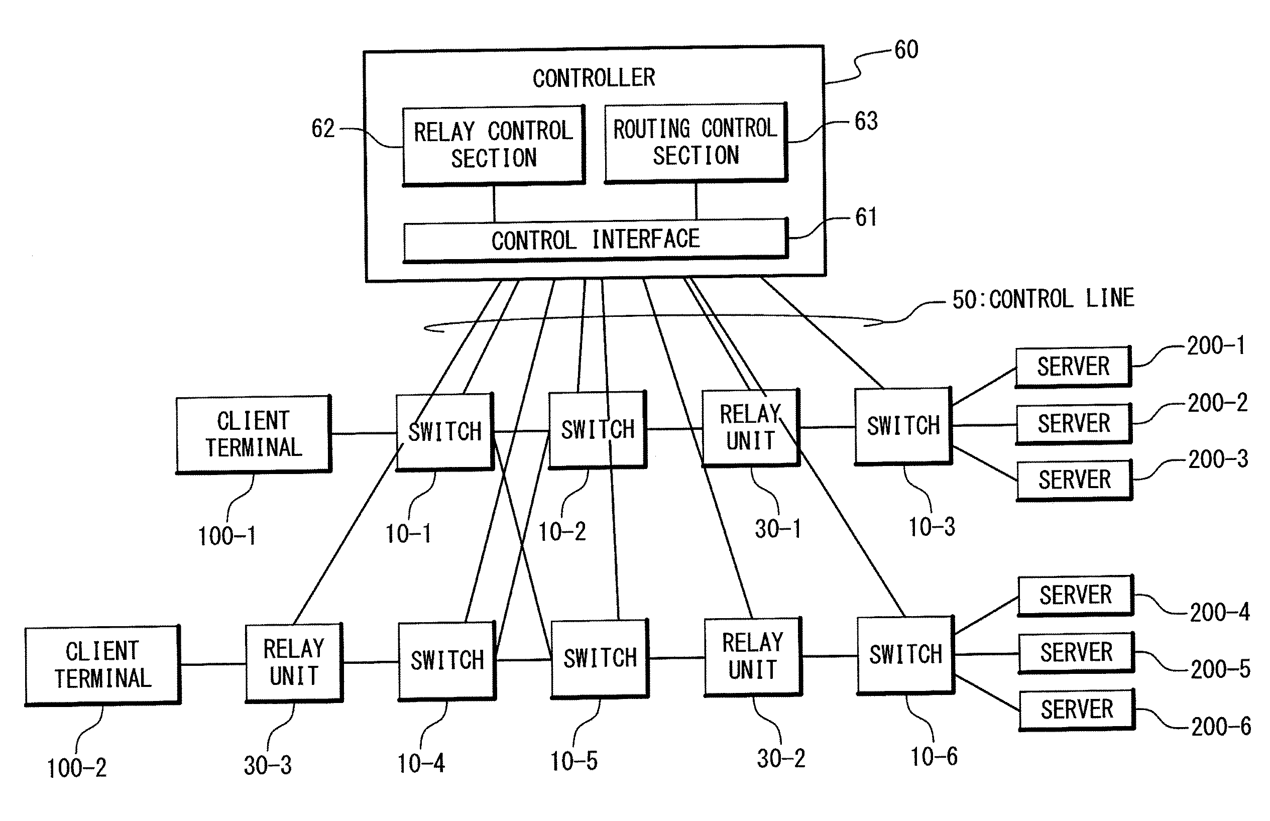
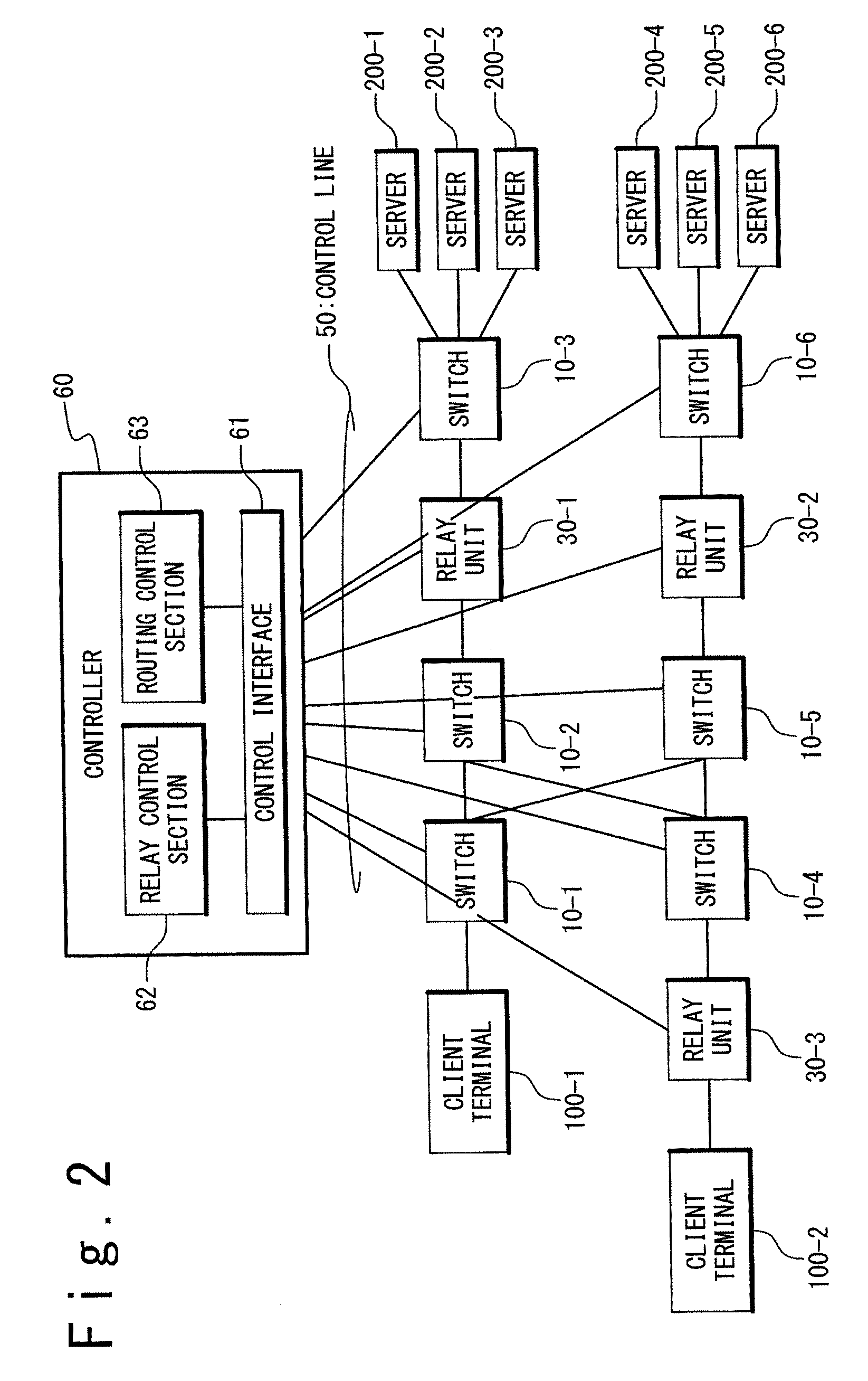
[0038]As shown in FIG. 2, an application switch system of the present invention is provided with client terminals 100 (100-=1 to N, N is an optional integer), switches 10 (10-i, i=1 to N), relay units 30, a control line 50, a controller 60, and servers 200 (200-i, i=1 to N).

[0039]The client terminals 100 are connected with the servers 200 through the switches 10 and the relay units 30. The switches 10 and the relay units 30 exist on a network. Here, it is supposed that the number of client terminals 100, the number of switches 10, the number of relay units 30 and the number of servers 200 are different. However, actually, the number of client terminals 100, the number of switches 10, the number of relay units 30 and the number of server 200 may be same.

[0040]The switch 10 is an application switch.

[0041]The relay unit 30 relays transmission data between t...

second exemplary embodiment

[0114]Next, a second exemplary embodiment of the present invention will be described.

[0115]In the present exemplary embodiment, the relay unit 30 and the server 200 are realized as applications of virtual machines (VM) on a computer not as independent units. A plurality of virtual machines operate on the server 200 and one of these virtual machines attains a relay function. The other virtual machines attain server functions. Thus, on the server 200, the relay function and the server function are connected by an internal network of the virtual machines.

[0116]Referring to FIG. 7, the server 200 is provided with a main function section 210, server function sections 220 (220-i, i=1-N) and a relay function section 230 in the present exemplary embodiment.

[0117]The main function section 210 contains a CPU 211 and a virtual machine monitor (VMM) (or Hypervisor) 212. In the main function section 210, the virtual machine monitor 212 operates on the CPU 211 and the server function sections 220...

first example

[0120]Referring to FIG. 8, a connection from the client terminal 100-1 to the server 200-3 in FIG. 2 will be described.

[0121](1) Step S101

[0122]The client terminal 100-1 issues a TCP connection request for receiving a service provided from the server 200. At this time, the initial state of the switch 10-1 is in the state of no flow entry. Therefore, miss hit occurs in the search of flow entries, and data indicating the miss hit is sent to the controller 60. Also, the controller 60 can communicate with the client terminal 100-1 through the switch 10-1. In the TCP connection request, the connection is established through a sequence called “3-way handshake”.

[0123](2) Step S102

[0124]When the connection is established, the client terminal 100-1 transmits request data to the controller 60.

[0125](3) Step S103

[0126]When receiving a data segment correctly, the controller 60 performs the TCP protocol processing on the data and returns an ACK for the position corresponding to a sequence number...


PUM


Abstract

In data processing of network traffic (a communication amount), relay processing is distributed in a wide area. Specifically, an application switch system which controls a connection between a plurality of client terminals and a plurality of servers, is provided with at least one switch, a relay unit configured to perform protocol relays; and a controller. The controller is provided with a section for performing a centralized control on a route table used to determine a destination in the switch; a section for controlling relay processing of the relay unit; a section for selecting one server as a connection destination from the plurality of servers; a section for selecting a route which links between one client terminal of the plurality of client terminals and the selected server, and which contains the relay unit, and for setting the selected route to the route table in the switch; and a section for setting relay information used when the relay unit performs the protocol relay, to the relay unit.

Description

CROSS-REFERENCE TO RELATED APPLICATION[0001]This is a continuation of International Application No. PCT / JP2010 / 051424, filed on Feb. 2, 2010.TECHNICAL FIELD[0002]The present invention is related to an application switch system, and more particularly to an application switch system which performs routing control on a network.RELATED ART[0003]Conventionally, a problem is known that a network route is not efficient when servers as switching destinations of an application switch are distributed.[0004]In Patent Literature 1 (U.S. Pat. No. 5,941,988), a technique is disclosed which two TCP (Transmission control Protocol) sessions called TCP splicing are relayed. The TCP splicing is a high-speed processing technique in a TCP proxy apparatus such as an application gateway, and the two TCP sessions using the TCP proxy is short-cut to relay processing in a packet level.[0005]Also, Patent Literature 2 (U.S. Pat. No. 7,000,027) is discloses a TCP splicing as another example. In Patent Literatur...

Claims


Application Information

Patent Timeline
IPC IPC(8): G06F15/16H04L45/42H04L47/40
CPCH04L45/42H04W40/22H04L69/163H04L67/1038H04L69/161H04L67/2814H04L67/563
Inventor UENO, HIROSHI
Owner NEC CORP
Why Eureka
Try Eureka