Gearbox

a gearbox and gearbox technology, applied in the field of gearboxes, can solve the problems of inflexible operation of worm-driven gearboxes, large gearboxes including worm-driven gearboxes for providing drive to the drive train, and large size of gearboxes

Inactive Publication Date: 2011-12-01
CORCOST LTD
View PDF3 Cites 12 Cited by
  • Summary
  • Abstract
  • Description
  • Claims
  • Application Information

AI Technical Summary

Benefits of technology

[0023]The toothed section may be attached to the drive rack nut or be formed integrally with the drive rack nut. Where the toothed section is attached to the drive rack nut, this may assist in the assembly of the gearbox. Furthermore, preferably the toothed section may be resiliently biased with respect to the drive rack nut, for example by the inclusion of a spring between the drive rack nut and the toothed section. This can bias the toothed section into or out of meshed engagement with the gear associated with the shaft. This can help ensure reliable meshing of the toothed section with the gear during normal operation to minimise wear and / or vibration.
[0027]The gearbox of the present invention allows the input of additional energy from an energy storage means to assist with the drive. In particular, the application of a force / motion on the toothed section or the drive rack nut and / or the gear and / or shaft can reduce the amount of force that must be applied to drive the leadscrew to move the drive rack nut along the leadscrew as well as rotate the gear and shaft. This is distinct from a worm drive arrangement in which the application of a force on the worm gear will not assist with the operation of the drive, and indeed will generally result in a force being applied between the worm and the worm gear which will need to be overcome to operate the worm drive, and will therefore increase the amount of force required to operate the worm drive. Whilst other gearbox arrangements may be able to utilise additional energy to assist with the driving of the output, these are generally not self-locking. Therefore an advantage of a preferred gearbox is that it is both able to self-lock whilst being able to utilise additional drive or energy.
[0030]The gearbox housing may be a single piece housing, although it is preferred that the housing comprises a plurality of components that are connectible together. In this case, it is preferred that one or more pieces of the housing are replaceable with other pieces having different properties, for example of different size. This allows the overall size of the housing to be varied depending upon the size of the components to be contained within the gearbox.

Problems solved by technology

This means that gearboxes including a worm drive for providing drive to the drive train are typically large.
In particular, the relative output to input is limited by the size of the gearbox.
This means that worm driven gearboxes are inflexible regarding their operation with narrow output ranges.
Worm driven gearboxes must be manufactured with tight tolerances, making them costly, and have a tendency to generate large amounts of excess heat making them inefficient and susceptible to wear.
This also means that the gearbox cannot “free wheel”.
This means that the worm driven gearbox is always fully engaged and therefore cannot be selectively engaged or disengaged.
Such gearboxes are susceptible to wear.

Method used


Image

  • Gearbox
  • Gearbox
  • Gearbox

Examples


first embodiment

[0096]FIG. 3 shows a collective where two gearboxes 1 according to the invention are coupled to each other. In this case the gearboxes 1 are coupled by the shaft 5 and / or other output means to form a collective output means 20. Each gearbox can work independently, although typically the gearboxes work together. The gearboxes can share the same housing 2 or can have separate housings 2. The gearboxes 1 can work harmoniously together even if the respective internals of the gearboxes 1, such as the drive train, actuator element, and / or outputs means as well as motion and force outputs and inputs are different, even if the gearboxes 1 are not the same. This is of an advantage that cannot be equalled by other known gearboxes.

[0097]Each gearbox 1 can have a different output means not only in terms of force and motion but also with regards to the size and shape. The gearboxes 1 can be attached to each other in axial alignment with relation to the output means 5 as shown in FIG. 3, or may b...

second embodiment

[0103]FIGS. 5A and 5B shows a gearbox 100. FIG. 5A shows a plan view and FIG. 5B shows a side view.

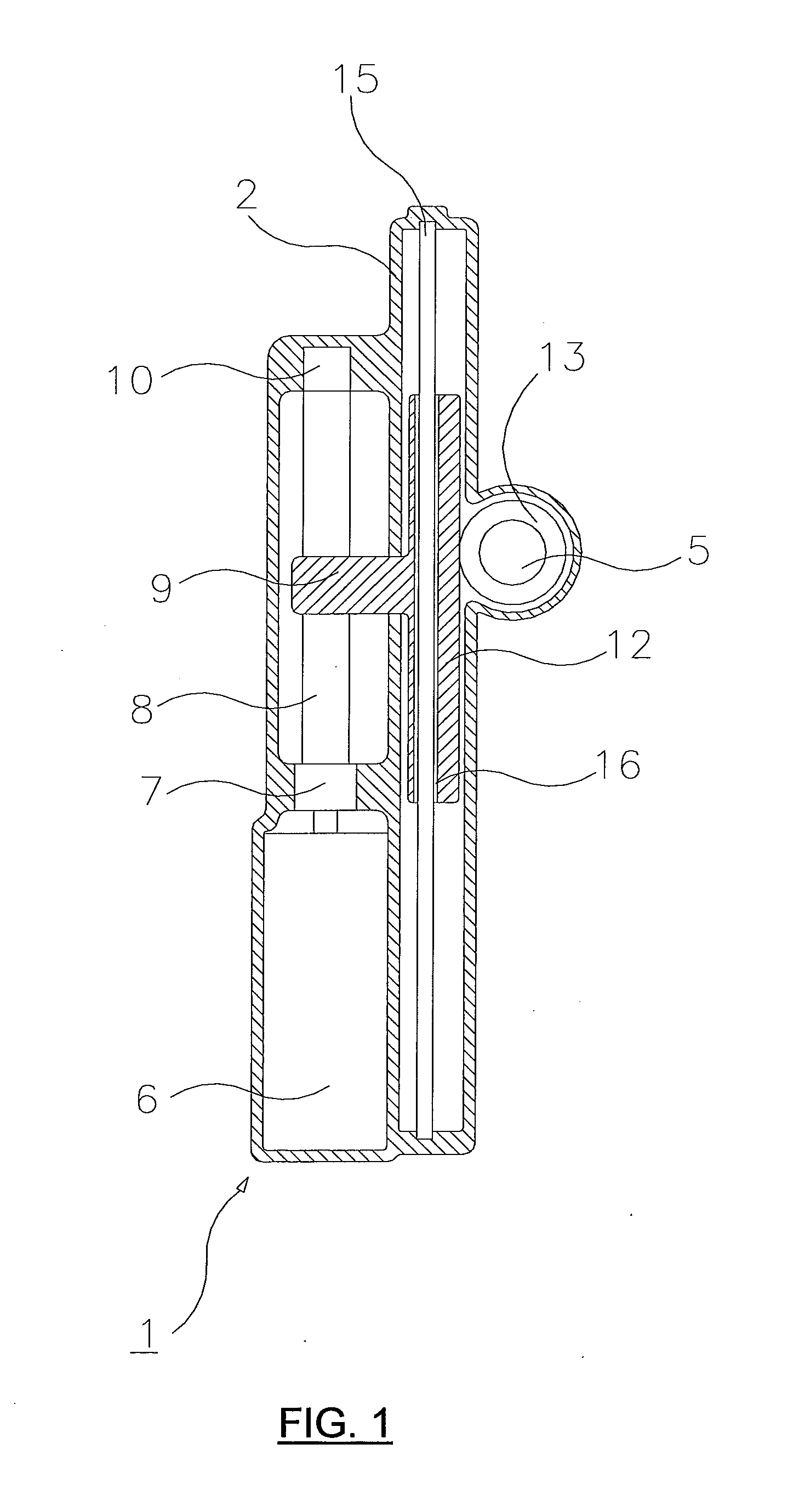
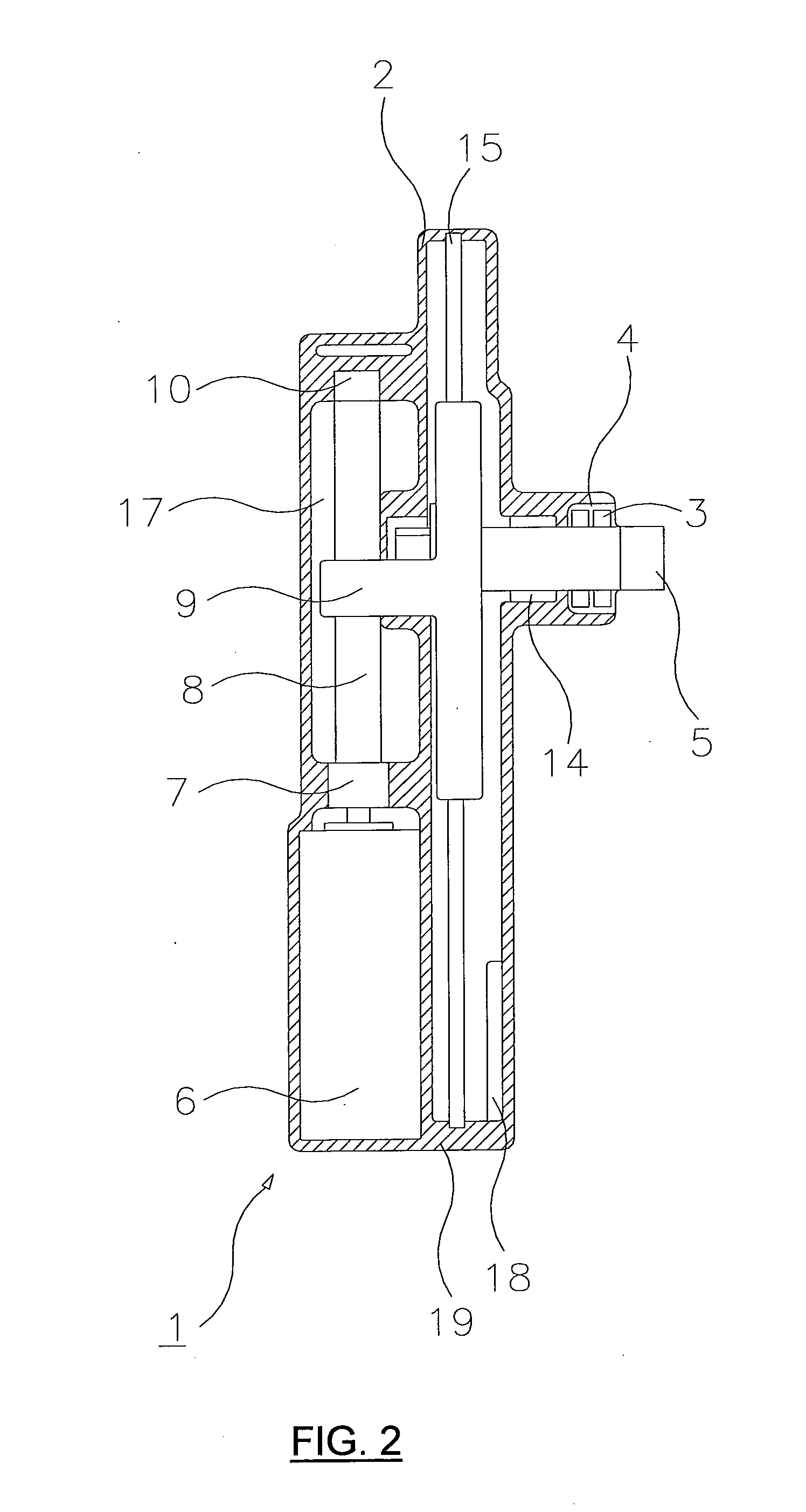
[0104]The gearbox 100 is similar to the gearbox shown in and described with respect to FIGS. 1 and 2. Therefore the numbering used is the same as for FIGS. 1 and 2 for the same components, and the description, alternative features and functions of the basic gearbox as described with respect to FIGS. 1 and 2 are not repeated.

[0105]The main difference between the gearbox 100 and that shown in FIGS. 1 and 2 is that of a drive train, such as additional gears, coupling the driven shaft 5 to a separate output shaft 105. In the example shown, the gear 13 is provided on shaft 5 which includes the first gear of the drive train, drive gear 22. The drive gear 22 meshes with an intermediate gear 23 provided on shaft 25, which in turn meshes with an output gear 24 provided on an output shaft 105 and in this case concluding the drive train. The output shaft 105 may extend through an end cap 104 simi...


PUM


Abstract

A gearbox having a housing, an actuator, a leadscrew rotated by the actuator, a rack nut threadingly engaged with the leadscrew to move longitudinally as the leadscrew rotates, a toothed section that moved with the rack nut, a shaft and a gear integral with or coupled to the shaft, and arranged such that rotation of the gear causes rotation of the shaft.

Description

[0001]Gearboxes have been used for many years and they have many different applications. Generally gearboxes comprise four main elements: actuator; drive train; housing and output means.[0002]The actuator places force and motion into the drive train. The actuator may be a motor connected to the drive train through suitable gearing, such as a spur, bevel, helical or worm gear.[0003]The drive train allows the manipulation of output motion and force with respect to the input motion and force provided by the actuator. The drive train typically comprises a plurality of gears of varying parameters such as different sizes, number of teeth, tooth type and usage, for example spur gears, helical gears, worm gears and / or internal or externally toothed gears.[0004]The gearbox housing is the means which retains the internal workings of the gearbox in the correct manner. For example it allows the actuator, drive train and output means to be held in the correct relationship for the desired operati...

Claims


Application Information

Patent Timeline
Patent Type & Authority Applications(United States)
IPC IPC(8): F16H59/02F16H59/00
CPCA61G5/1056A61G7/018F16H19/04F16H25/20Y10T74/18576Y10T74/20018Y10T74/2014Y10T74/2003Y10T74/19565
Inventor CORCORAN, STEVEN
Owner CORCOST LTD
Why Eureka
Try Eureka