Multipoint servo press machine

a servo press machine and multi-point technology, applied in the direction of presses, presses, manufacturing tools, etc., can solve the problems of inability to ensure the alignment between the two points, the delay of torque transmission, and the transient delay of the transmission, so as to reduce the gear backlash, reduce the positional precision, and the effect of good respons

Inactive Publication Date: 2011-12-01
AIDA ENG LTD
View PDF5 Cites 13 Cited by
  • Summary
  • Abstract
  • Description
  • Claims
  • Application Information

AI Technical Summary

Benefits of technology

[0022]The servo press machine incorporating the power transmission mechanism of the invention is adapted to reduce the gear backlash because the machine can utilize the synchronous distribution gear for synchronizing the main gears while directly applying the torque to the individual main gears. The gear backlash is small as the result of elimination of the exclusive gear for synchronization and hence, the machine surfers less decrease in positional precision for the slide, achieving good response. Further, the machine can drive by means of a small number of gears and hence, the machine has a simple structure and low loss. Further, the machine can be downsized and is accordingly reduced in inertia moment so as to be capable of high speed response.

Problems solved by technology

Although such connection methods can distribute force no the two pressure points (crank structures), the following problem is encountered in a case where the individual points do not receive the same load due to eccentric load or the like.
Since the number of gears is increased by interposing the intermediate gear, the total sum of gear backlash is increased, causing delay in torque transmission.
This leads to a transient delay in the transmission of the load difference between the points so that precision alignment between the two points cannot be ensured (levelness of the slide is not obtained).
There is another problem that the need for adding the exclusive intermediate gear for synchronization results in a corresponding increase in torque loss and also in an increased size of the machine.
This results in a problem of further increase in the backlash.

Method used


Image

  • Multipoint servo press machine
  • Multipoint servo press machine
  • Multipoint servo press machine

Examples


embodiment 1

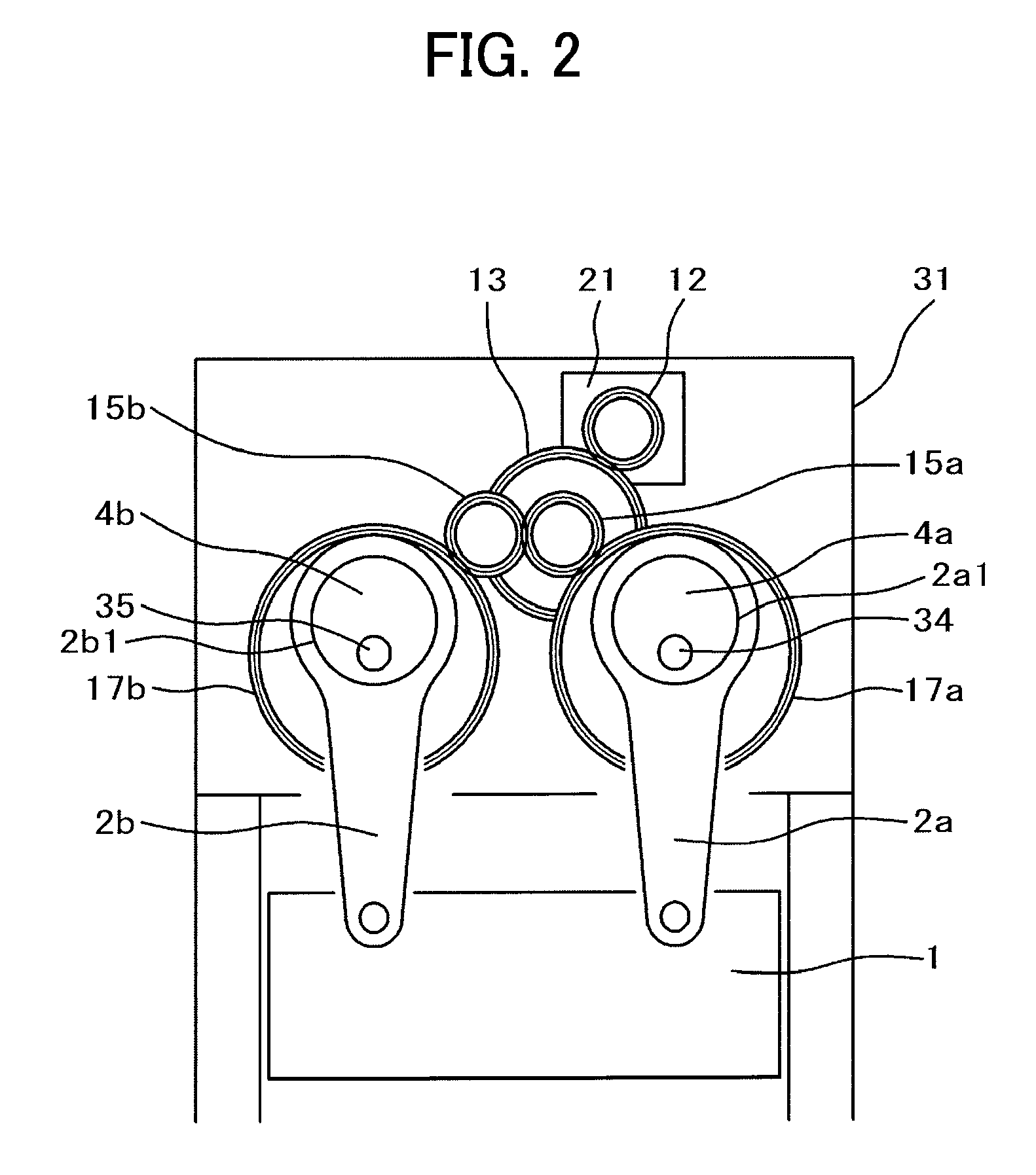
[0033]An exemplary configuration of a servo press according to an embodiment 1 practicing the principle of FIG. 1 is shown in FIG. 2 and FIG. 3. The figures schematically depict relevant parts of the embodiment of the invention. The figures show a structure of an eccentric press.

[0034]A servo motor 21 is mounted to a frame 31 of the servo press machine. An output shaft of the servo motor 21 is coupled to a drive shaft 11. A drive gear 12 is mounted to the drive shaft 11. The frame 31 is provided with a pin 32, the opposite ends of which are fixed to the frame 31. The pin 32 is engaged with a synchronous distribution shaft 14a, to which a large synchronous distribution gear 13 and a small synchronous distribution gear (first small synchronous distribution gear) 15a are mounted. The small synchronous distribution gear 15a and the large synchronous distribution gear 13 are integrally formed so as to be rotated in synchronism. The large synchronous distribution gear 13 is meshed with th...

embodiment 2

[0046]FIG. 4 and FIG. 5 are configuration diagrams illustrating an embodiment 2 of the invention. The embodiment is of a two-point support type and each of the points is driven by two con rods. FIG. 4 is a schematic front view of the embodiment while FIG. 5 is a schematic top plan view thereof.

[0047]A servo motor 321a is mounted to a frame 331 of a servo press machine. An output shaft of the servomotor 321a is coupled to a drive shaft 311a, to which a drive gear 312a is mounted. The frame 331 is provided with a pin 332 (not shown), the opposite ends of which are fixed to the frame 331. The pin 332 is engaged with a synchronous distribution shaft 314a. Mounted so the synchronous distribution shaft 314a are a large synchronous distribution gear (first large synchronous distribution gear) 313a and a small synchronous distribution gear (first small synchronous distribution gear) 315a. The large synchronous distribution gear 313a is meshed with the above drive gear 312a.

[0048]A pin 334 ...

embodiment 3

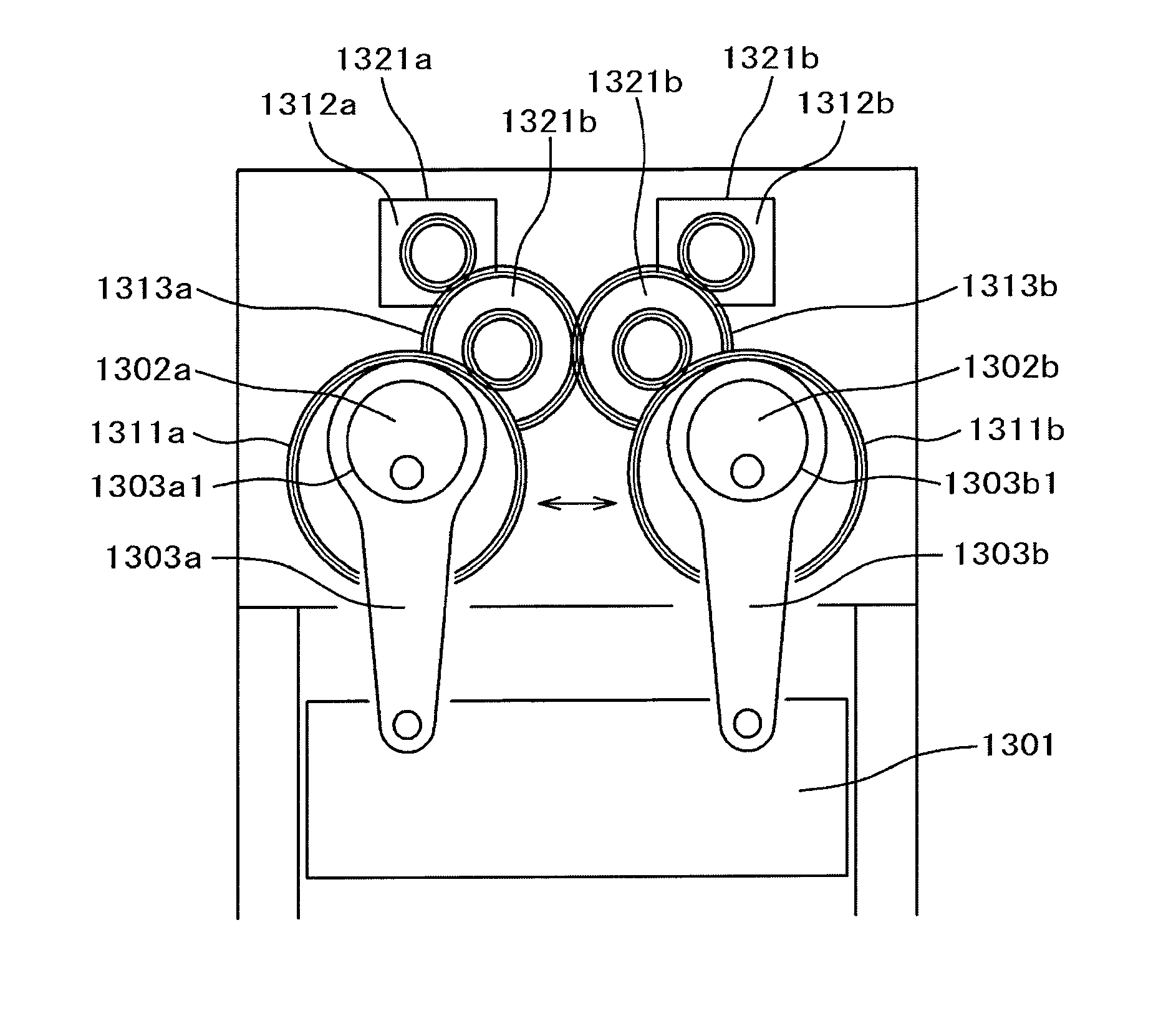
[0066]FIG. 7 is a configuration diagram of an embodiment 3 of the invention. The configuration differs from that of the embodiment 2 in the manner of meshing engagement of the synchronous distribution gears for synchronizing the main gears.

[0067]An eccentric portion of an eccentric ring 1302a engages with a hole 1303a1 in a large diameter portion of a con rod 1303a. A lower end of the con rod 1303a is coupled to a slide 1301. An eccentric portion of an eccentric ring 1302b engages with a hole 1303b1 in a large diameter portion of a con rod 1303b. A lower end of the con rod 1303b is coupled to the slide 1301. The eccentric rings 1302a, 1302b are connected to a main gear 1311a (one of the main gear pair) and a main gear 1311b (the other one of the main gear pair) at one end thereof, respectively.

[0068]The main gear 1311a is meshed with a small synchronous distribution gear (first small synchronous distribution gear) 1314a. Connected to a shaft of this synchronous distribution gear is ...


PUM


Abstract

The invention provides a servo press machine including a slide moved up and down by multiple crank structures, the machine which provides perfect synchronism between main gears driving the respective crank structures and in which a compact, efficient power transmission structure can be implemented in a simple construction. In the servo press machine including the slide moved up and down by the multiple crank structures, synchronous distribution gears are driven by servo motors; the multiple main gears are driven in synchronism by the synchronous distribution gears; and each of the crank structures is driven by each of the main gears.

Description

BACKGROUND OF THE INVENTION[0001]1. Field of the Invention[0002]The present invention relates to a servo press machine and more particularly, to a large servo press machine adapted for pressing with multiple points.[0003]2. Description of Related Art[0004]The servo press machine driven by a servo motor is capable of making various slide motions, which are utilized for various purposes. For example, the servo press machine may slow down the slide motion just prior to press load thereby facilitating drawing or may slow down the slide motion during press load thereby reducing noises. Further, the servo press machine contributes to productivity enhancement by working in a so-called pendular operating mode wherein a slide is moved up and down near a bottom dead point thereof. The large servo press machine adopts a multipoint drive method of pressing the slide with multiple points. Accordingly, the servo press machine employs a system wherein main gears for driving respective points are d...

Claims


Application Information

Patent Timeline
Patent Type & Authority Applications(United States)
IPC IPC(8): B30B1/00
CPCB30B15/148B30B1/266
Inventor ITO, TAKAOKOSHIMIZU, TAKASHINAGASE, HIROSHI
Owner AIDA ENG LTD
Why Eureka
Try Eureka