Method and apparatus for the conversion of aquatic plants into biogases and electricity

Inactive Publication Date: 2011-12-01
SSB INT
View PDF5 Cites 25 Cited by
  • Summary
  • Abstract
  • Description
  • Claims
  • Application Information

AI Technical Summary

Problems solved by technology

However, the production of biogases can often be costly and can result in was

Method used


Image

  • Method and apparatus for the conversion of aquatic plants into biogases and electricity
  • Method and apparatus for the conversion of aquatic plants into biogases and electricity
  • Method and apparatus for the conversion of aquatic plants into biogases and electricity

Examples


Embodiment Construction

[0016]Certain terminology is used in the following description for convenience only and is not limiting. The words “right”, “left”, “lower” and “upper” designate directions in the drawings to which reference is made. The words “inwardly” and “outwardly” refer to directions toward and away from, respectively, the geometric center of the system and designated parts thereof. Unless specifically set forth herein, the terms “a”, “an” and “the” are not limited to one element but instead should be read as meaning “at least one”. The terminology includes the words noted above, derivatives thereof and words of similar import.

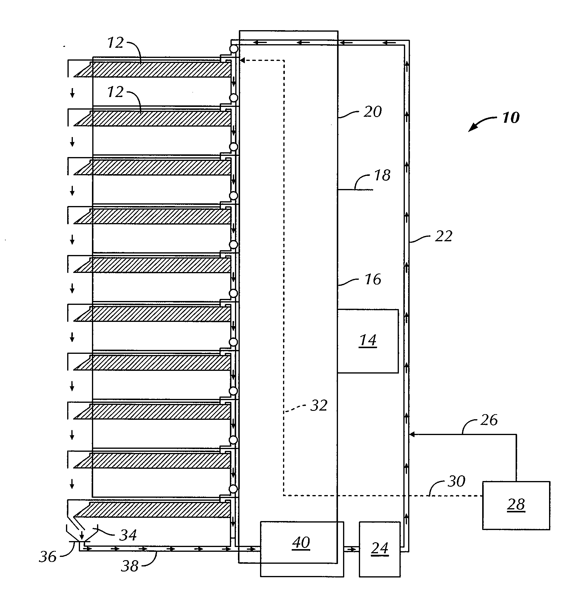
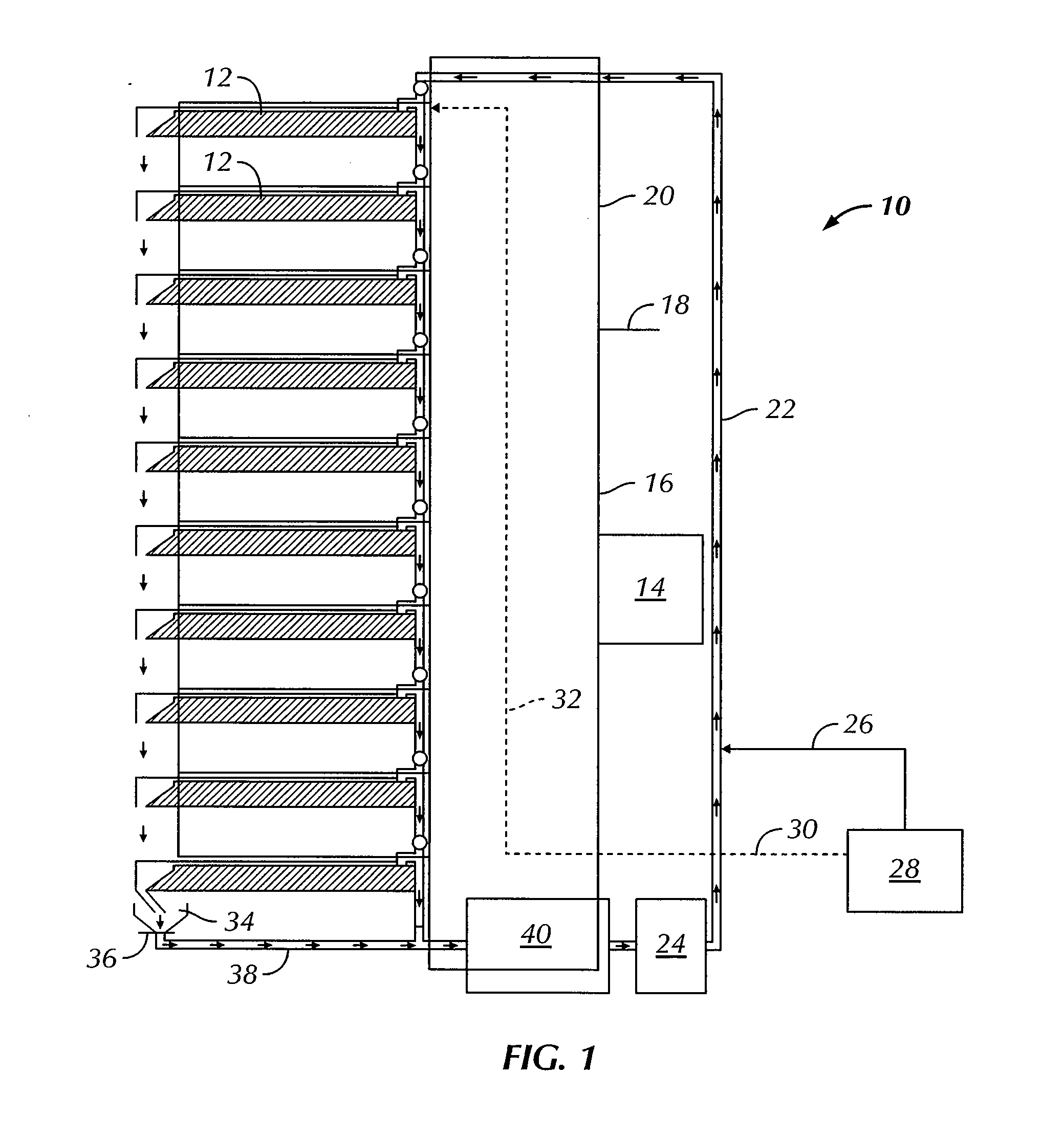
[0017]Referring to the drawings in detail, wherein like numerals and characters indicate like elements throughout, there is shown in FIG. 1 a growth system 10 in accordance with a preferred embodiment of the present invention. With reference to FIGS. 3-4, there is shown a gasifier 42 in accordance with a preferred embodiment of the present invention.

[0018]The present inv...


PUM


Abstract

A method for producing a biogas is provided. The method includes the steps of providing a polyculture of aquatic plants to a growth system; continuously providing water, carbon dioxide, air and nutrients to the polyculture contained within the growth system; growing the polyculture for a time sufficient to produce an aquatic plant-based biomass; withdrawing a portion of the aquatic plant-based biomass contained within the growth system; and treating the withdrawn aquatic plant-based biomass to produce a biogas.

Description

CROSS-REFERENCE TO RELATED APPLICATIONS[0001]This application claims the benefit of U.S. Provisional Patent Application No. 61 / 343,205, filed Apr. 26, 2010, the entire contents of which are incorporated by reference herein.BACKGROUND OF THE INVENTION[0002]The present invention relates to the production of synthetic fuels, also known as synfuels, and, more particularly, to the production of a plant-based and methane-containing biogas. Biogas can be obtained or produced from various organic or agricultural matter and is useful as a low-cost fuel for heating or energy production purposes. However, the production of biogases can often be costly and can result in waste products and exhaust gases that require further treatment and / or disposal.[0003]Accordingly, it is desirable to provide a method for producing a biogas which is efficient, sustainable, and which results in a minimal amount of waste products.BRIEF SUMMARY OF THE INVENTION[0004]Briefly stated, in one embodiment, the present ...

Claims


Application Information

Patent Timeline
IPC IPC(8): F02B43/08A01G1/00A01G9/02C12N1/12
CPCC12N1/12C12P5/023C12M21/04A01G31/06Y02E50/343Y02E50/30
Inventor SMITH, MICHAEL J.GAINE, EDWARD WILLIAM
Owner SSB INT
Why Eureka
Try Eureka