Heat Exchanger with heat exchange chambers utilizing respective medium directing members

a technology of heat exchange chambers and heat exchange media, which is applied in the direction of lighting and heating apparatus, tubular elements, and stationary conduit assemblies, etc. it can solve the problems of reduced pressure resistance, increased surface area, and limited efficiency of pipe heat exchangers, so as to enhance heat exchange capabilities and increase surface area. , the effect of increasing the surface area

Inactive Publication Date: 2011-12-01
MIKUTAY CORP
View PDF4 Cites 4 Cited by
  • Summary
  • Abstract
  • Description
  • Claims
  • Application Information

AI Technical Summary

Benefits of technology

[0011]In another embodiment of the present invention, more than one chamber may be used, which will further increase the surface area of the enhanced tube for the heat exchanger. Also, a first chamber may be connected directly to another chamber.
[0012]In yet another embodiment of the present invention, the tube size may vary between the chambers, and if more than one chamber is used, the chamber size may vary from one chamber to the next.
[0013]In a further embodiment of the present invention, each chamber may disperse heat exchanging media throughout the chamber, which further enhances the heat exchanging capabilities of the present invention. Also, each chamber may also mix heat exchanging media.
[0014]In yet a further embodiment of the present invention, each chamber may include a medium directing member and medium redirection members that direct and redirect heat exchanging me

Problems solved by technology

The efficiency of the pipe heat exchangers is limited by the amount of surface area available for the transfer of heat.
However, the pressure resistance is reduced, and the thinner tubes are more prone to damage.
Also, the assembly process is complicated because of the fragile nature of the parts.
In addition, the internal chambers are prone to plugging during the manufacturing process, particularly if a brazing process is utilized.
The complexity of the extruding process potentially results in higher costs and higher defect rates.
Also, by utilizing internal c

Method used


Image

  • Heat Exchanger with heat exchange chambers utilizing respective medium directing members
  • Heat Exchanger with heat exchange chambers utilizing respective medium directing members
  • Heat Exchanger with heat exchange chambers utilizing respective medium directing members

Examples


Embodiment Construction

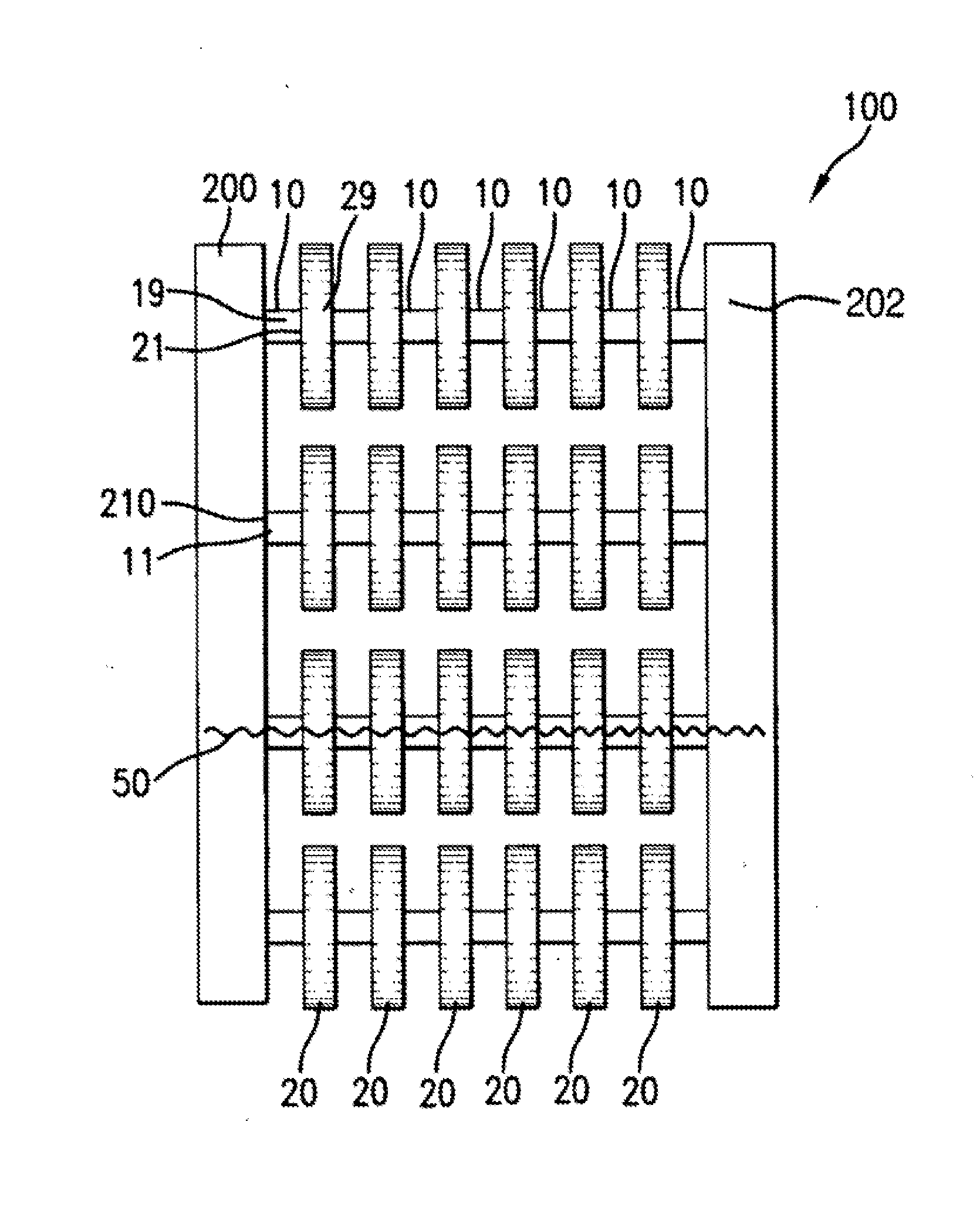
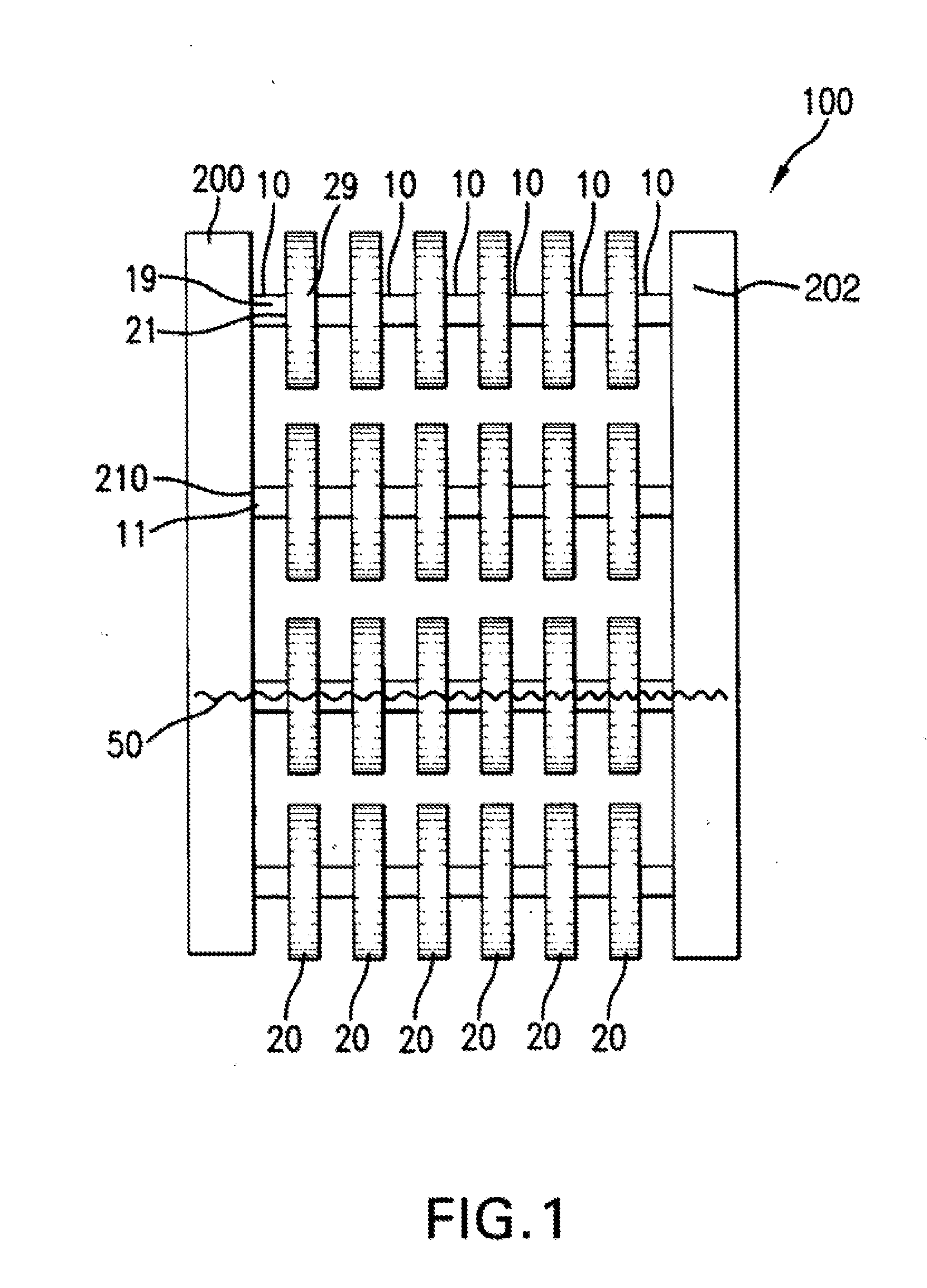
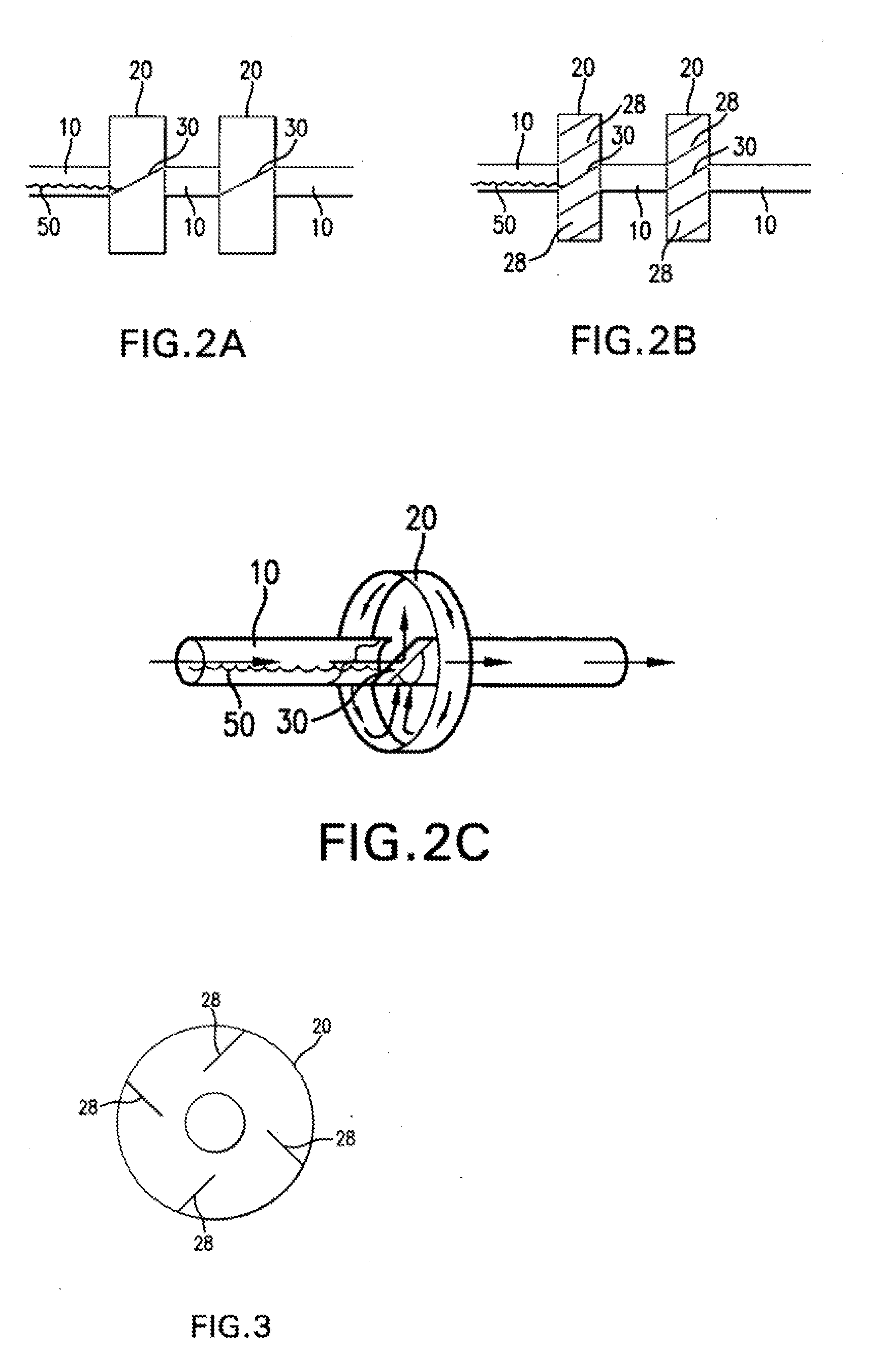
[0040]Referring to the drawings and in particular FIG. 1, an embodiment of a heat exchanger 100 is shown. The heat exchanger 100 includes a manifold 200 matingly engaged to free ends of tubes 10 that are brazed together to redirect chambers 20. As shown in FIG. 1, the redirect chambers 20 have a greater fluid capacity than the tubes 10. Heat exchange media 50 flows from the outlet 210 of the manifold 200 into the inlet 11 of the tube 10. The heat exchange medium 50 passes through the outlet 19 of the tube 10 into the inlet 21 of the redirect chamber 20. The heat exchange media 50 then flows out an outlet 29 of the redirect chamber 20. The process of going from a tube 10 to a redirect chamber 20 may repeat several times until the heat exchange media 50 is received by another manifold 202. There may also be several rows of the tube 10 and redirect chamber 20 combinations. Also, one embodiment may allow for just one tube 10 and one redirect chamber 20. Throughout the transport of the h...


PUM


Abstract

A heat exchange unit having a plurality of chamber units, said chamber units including an inlet orifice member, an outlet orifice member, and a plurality of walls defining a chamber interior, said chamber interior having lateral walls with plurality of protrusion members. The inlet receives a heat exchange medium flowing in a first flow direction in an initial line of low. Disposed within the chamber interior is a medium directing member, having an inclined surface, diverting the heat exchange medium from the initial flow direction so that it disperses within the chamber interior, in to at least two distinct flow patterns. The chamber interior having plurality of protrusion members on lateral walls of said interior, further causing the dispersion of heat exchange medium flow, causing turbulent flow pattern within the chamber interior. The heat exchange medium exits the chamber, via the outlet, in the initial line of flow. The chambers are interconnected by tubes to form assemblies. Plurality of chambers is arranged between manifolds to complete the medium flow.

Description

CROSS-REFERENCE TO RELATED APPLICATION[0001]This application is a continuation in part of pending U.S. Patent Office patent application No. 12 / 148,655 (filed on Apr. 21, 2008), the entire content of which is incorporated herein by reference.BACKGROUND OF THE INVENTION[0002]1. Field of the Invention[0003]The present invention relates generally to heat exchangers and, more specifically, to a tube and chamber apparatus for transporting heat exchange media.[0004]2. Discussion of the Related Art[0005]Heat exchangers are commonly utilized in systems where it is desired for heat to be removed. Typical basic heat exchangers are made of pipes, which channel heat exchanging media. Headers or manifolds are attached to each end of the pipes. These headers and manifolds act as receptacles for the heat exchanging media. The efficiency of the pipe heat exchangers is limited by the amount of surface area available for the transfer of heat.[0006]To add more surface area, some heat exchangers, such a...

Claims


Application Information

Patent Timeline
IPC IPC(8): F28F1/10F28F9/02
CPCF28D1/04F28F1/006F28F9/02F28F2009/222F28F1/10F28F13/08
Inventor NITTA, MINORUNITTA, TAKEYOSHI
Owner MIKUTAY CORP
Why Eureka
Try Eureka